Sliding Extension Wing
Right Wing used on Models BTC, LSA and LSB Left Wing used on Model LSB
Assembly (if required)
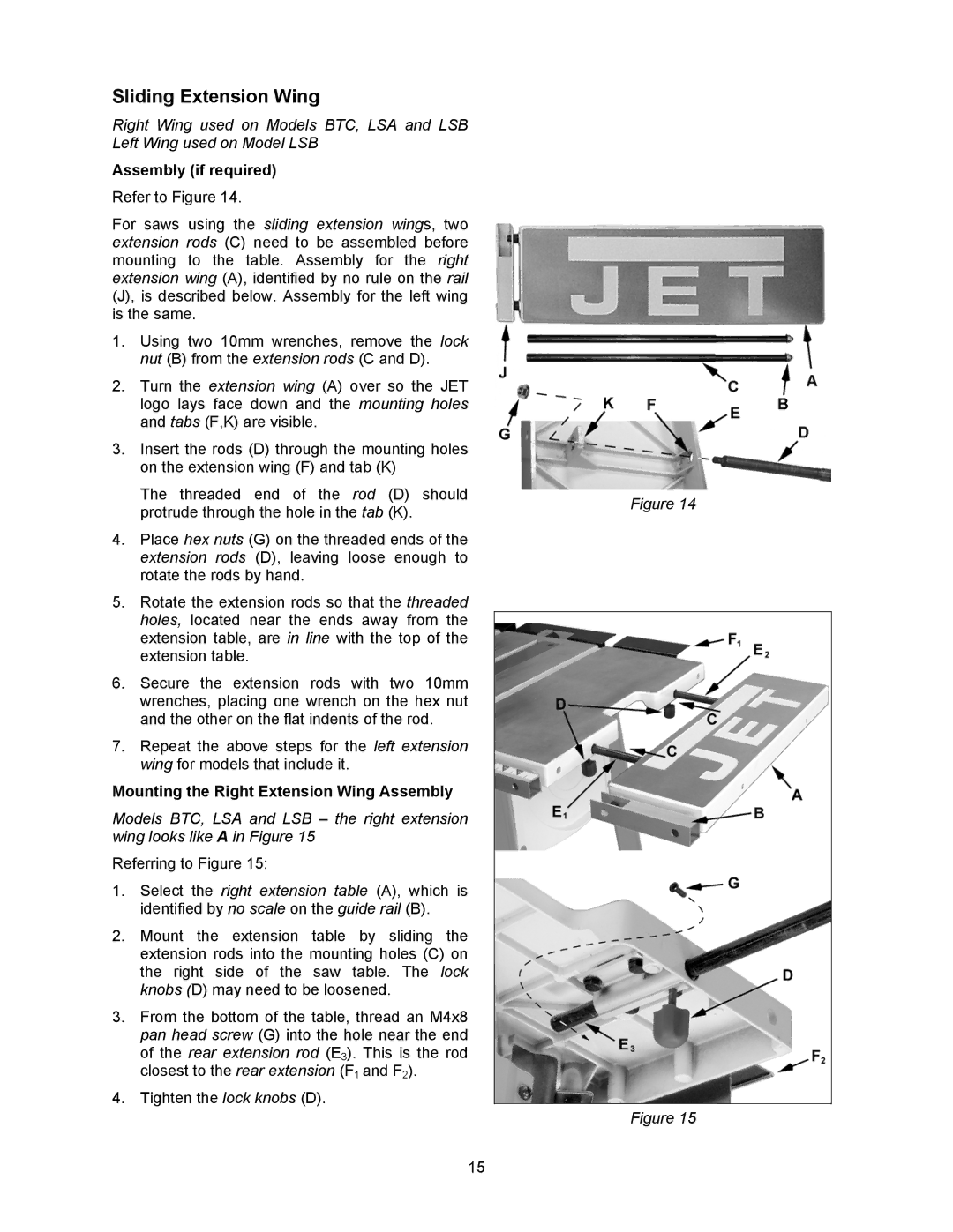
Refer to Figure 14.
For saws using the sliding extension wings, two extension rods (C) need to be assembled before mounting to the table. Assembly for the right extension wing (A), identified by no rule on the rail (J), is described below. Assembly for the left wing is the same.
1.Using two 10mm wrenches, remove the lock nut (B) from the extension rods (C and D).
2.Turn the extension wing (A) over so the JET logo lays face down and the mounting holes and tabs (F,K) are visible.
3.Insert the rods (D) through the mounting holes on the extension wing (F) and tab (K)
The threaded end of the rod (D) should protrude through the hole in the tab (K).
4.Place hex nuts (G) on the threaded ends of the extension rods (D), leaving loose enough to rotate the rods by hand.
5.Rotate the extension rods so that the threaded holes, located near the ends away from the extension table, are in line with the top of the extension table.
6.Secure the extension rods with two 10mm wrenches, placing one wrench on the hex nut and the other on the flat indents of the rod.
7.Repeat the above steps for the left extension wing for models that include it.
Mounting the Right Extension Wing Assembly
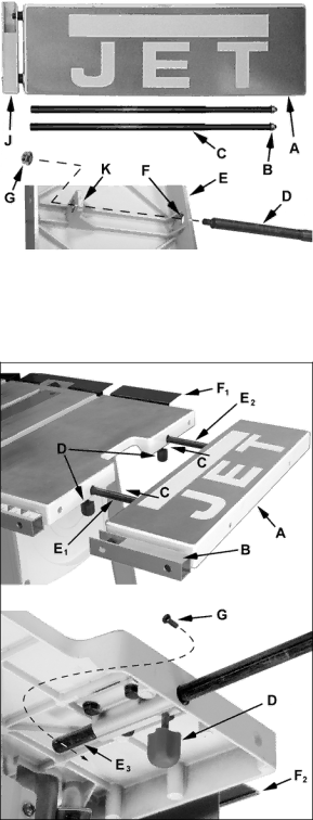
Models BTC, LSA and LSB – the right extension wing looks like A in Figure 15
Referring to Figure 15:
1.Select the right extension table (A), which is identified by no scale on the guide rail (B).
2.Mount the extension table by sliding the extension rods into the mounting holes (C) on the right side of the saw table. The lock knobs (D) may need to be loosened.
3.From the bottom of the table, thread an M4x8 pan head screw (G) into the hole near the end of the rear extension rod (E3). This is the rod closest to the rear extension (F1 and F2).
4.Tighten the lock knobs (D).
15
Figure 14
Figure 15