Mounting the Shelf
Models LSA, LSB
Note: The shelf is easier to install when three legs have been assembled. The fourth leg should be assembled after this section is completed.
Required hardware (for assembling all four legs): four M6 flange hex nuts (J).
Referring to Figure 3:
1.While the saw is still upside down, position the shelf (A) between the three legs (B) and below the legs' mounting tabs (D). The sides of the shelf (D) should point down.
2.Bring the shelf up, positioning the tabs of shelf
(E) against the bottom of the mounting tabs on the legs (C), and line up the mounting holes.
3.From underneath the shelf, insert a hex cap screw (F) up through the mounting holes of the shelf and leg tabs. Secure the threaded portion of the screw protruding through the top side of the leg mounting tab with a flange hex nut (J),
After the shelf is secured to all three legs, assemble the final leg (described in previous section) and then finish by securing the remaining shelf tab to the leg as well.
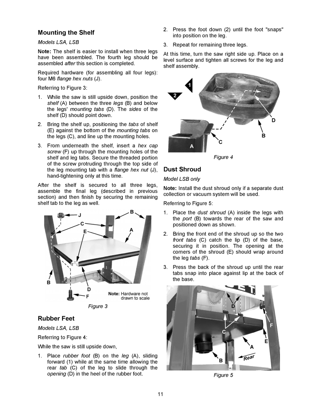
2.Press the foot down (2) until the foot "snaps" into position on the leg.
3.Repeat for remaining three legs.
At this time, turn the saw right side up. Place on a level surface and tighten all screws for the leg and shelf assembly.
Figure 4
Dust Shroud
Model LSB only
Note: Install the dust shroud only if a separate dust collection or vacuum system will be used.
Referring to Figure 5:
1.Place the dust shroud (A) inside the legs with the port (B) towards the rear of the saw and positioned down as shown.
2.Bring the front end of the shroud up so the two front tabs (C) catch the lip (D) of the base, securing it in position. The opening at the corners of the shroud (E) should wrap around the leg tabs (F).
3.Press the back of the shroud up until the rear tabs snap into place against lip at the back of the base.
Figure 3
Rubber Feet
Models LSA, LSB
Referring to Figure 4:
While the saw is still upside down,
1.Place rubber foot (B) on the leg (A), sliding forward (1) while at the same time allowing the rear tab (C) of the leg to slide through the
opening (D) in the heel of the rubber foot. | Figure 5 |
11