![]() Read and understand all assembly instructions before attempting assembly. Failure to comply may cause serious injury.
Read and understand all assembly instructions before attempting assembly. Failure to comply may cause serious injury.
![]() The main saw unit is heavy; use of an assistant is highly recommended when moving or turning it right side up.
The main saw unit is heavy; use of an assistant is highly recommended when moving or turning it right side up.
Tools required for assembly:
4mm hex key
10mm
Rubber mallet (for wing adjustment) Cross point (Phillips) screwdriver
8.2Unpacking and cleanup
1.Remove all contents from shipping carton. Keep saw table upside down (see Figure 5), and place a
2.Inspect contents for shipping damage. Report damage, if any, to your distributor.
3.Compare contents of shipping carton with the contents list in this manual. Report shortages, if any, to your distributor.
8.3Installing legs
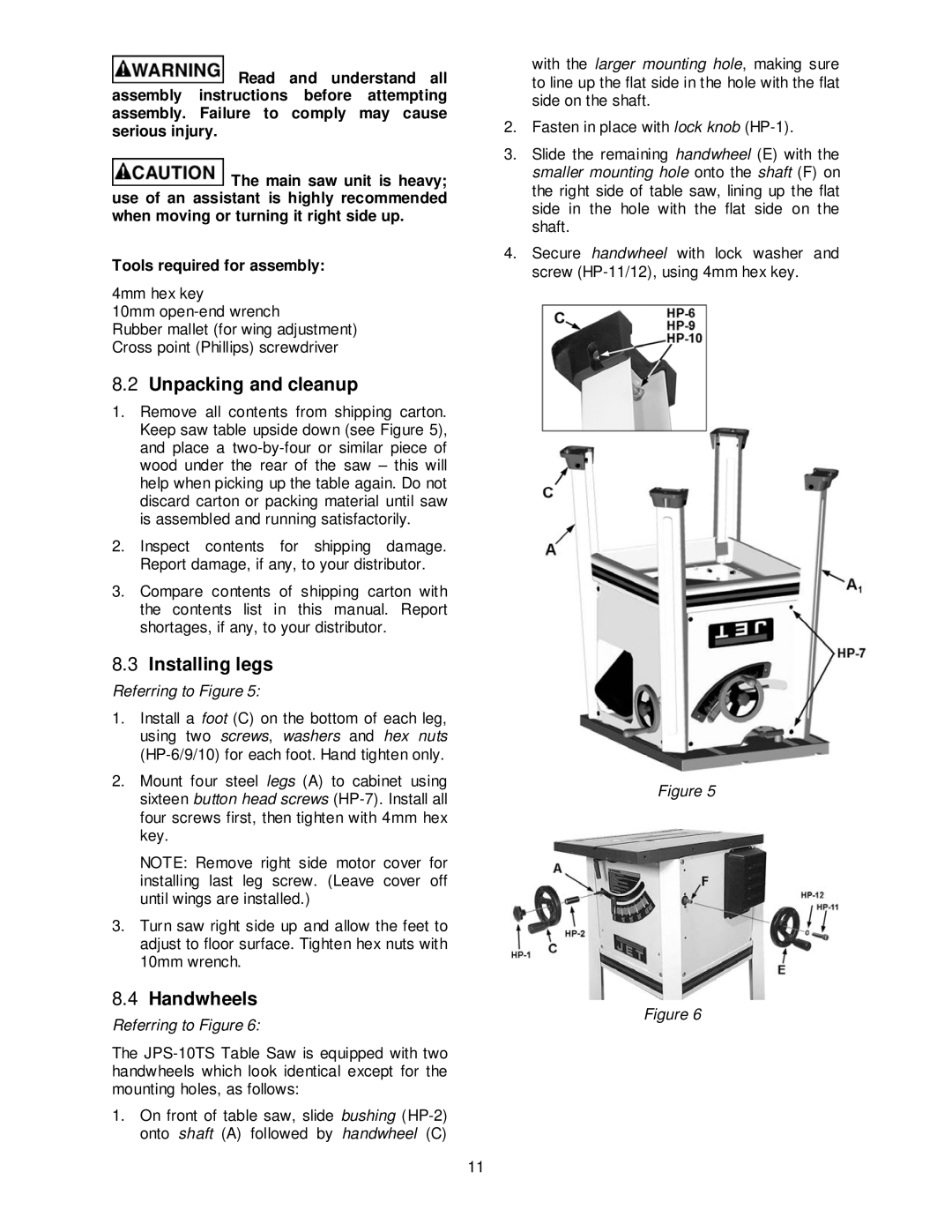
Referring to Figure 5:
1.Install a foot (C) on the bottom of each leg, using two screws, washers and hex nuts
2.Mount four steel legs (A) to cabinet using sixteen button head screws
NOTE: Remove right side motor cover for installing last leg screw. (Leave cover off until wings are installed.)
3.Turn saw right side up and allow the feet to adjust to floor surface. Tighten hex nuts with 10mm wrench.
8.4Handwheels
Referring to Figure 6:
The
1.On front of table saw, slide bushing
with the larger mounting hole, making sure to line up the flat side in the hole with the flat side on the shaft.
2.Fasten in place with lock knob
3.Slide the remaining handwheel (E) with the smaller mounting hole onto the shaft (F) on the right side of table saw, lining up the flat side in the hole with the flat side on the shaft.
4.Secure handwheel with lock washer and screw
Figure 5
Figure 6
11