3.Set blade 90º to table by turning blade tilting handwheel (D, Figure 23) counterclockwise as far as it will go. Do not force beyond stop.
4.Place a square (A, Figure 24) on the table and verify that blade (B, Figure 24) is at 90º to table. Make sure that the square is not touching a blade tooth.
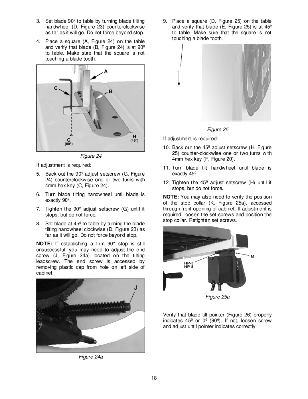
9.Place a square (D, Figure 25) on the table and verify that blade (E, Figure 25) is at 45º to table. Make sure that the square is not touching a blade tooth.
Figure 24
If adjustment is required:
5.Back out the 90º adjust setscrew (G, Figure
24)counterclockwise one or two turns with 4mm hex key (C, Figure 24).
6.Turn blade tilting handwheel until blade is exactly 90º.
7.Tighten the 90º adjust setscrew (G) until it stops, but do not force.
8.Set blade at 45º to table by turning the blade tilting handwheel clockwise (D, Figure 23) as far as it will go. Do not force beyond stop.
NOTE: If establishing a firm 90° stop is still unsuccessful, you may need to adjust the end screw (J, Figure 24a) located on the tilting leadscrew. The end screw is accessed by removing plastic cap from hole on left side of cabinet.
Figure 24a
Figure 25
If adjustment is required:
10.Back out the 45º adjust setscrew (H, Figure
25)
11.Turn blade tilt handwheel until blade is exactly 45º.
12.Tighten the 45º adjust setscrew (H) until it stops, but do not force.
NOTE: You may also need to verify the position of the stop collar (K, Figure 25a), accessed through front opening of cabinet. If adjustment is required, loosen the set screws and position the stop collar. Retighten set screws.
Figure 25a
Verify that blade tilt pointer (Figure 26) properly indicates 45º or 0º (90º). If not, loosen screw and adjust until pointer indicates correctly.
18