Figure 10
8.11Riving knife
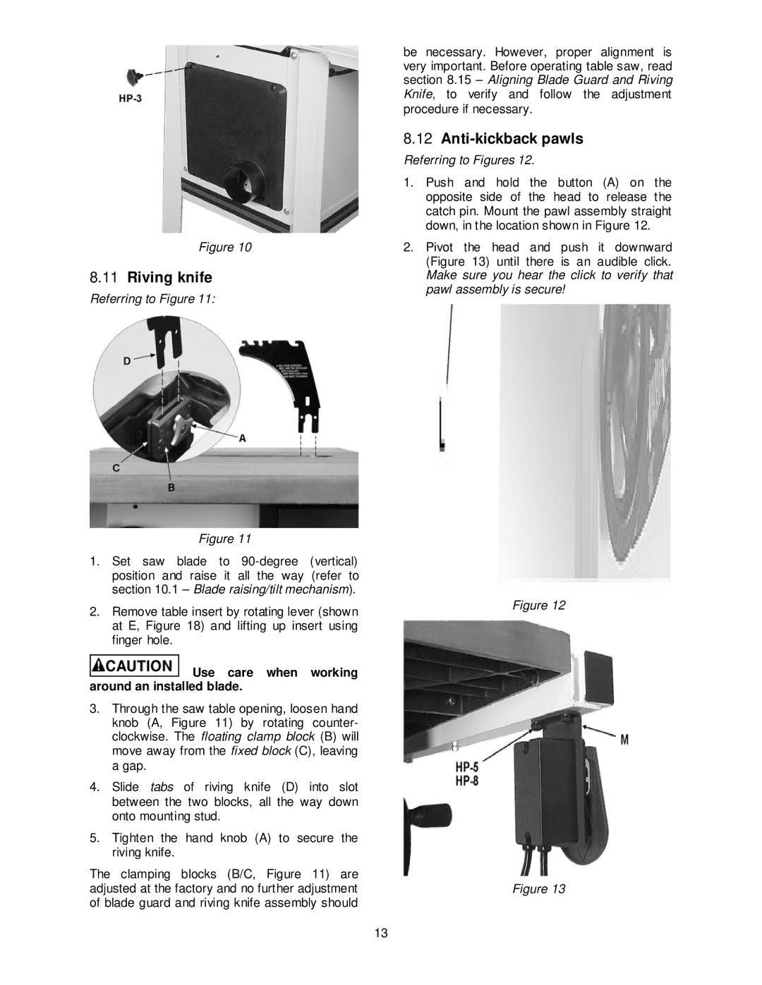
Referring to Figure 11:
Figure 11
1.Set saw blade to
2.Remove table insert by rotating lever (shown at E, Figure 18) and lifting up insert using finger hole.
 Use care when working around an installed blade.
3.Through the saw table opening, loosen hand knob (A, Figure 11) by rotating counter- clockwise. The floating clamp block (B) will move away from the fixed block (C), leaving a gap.
4.Slide tabs of riving knife (D) into slot between the two blocks, all the way down onto mounting stud.
5.Tighten the hand knob (A) to secure the riving knife.
The clamping blocks (B/C, Figure 11) are adjusted at the factory and no further adjustment of blade guard and riving knife assembly should
be necessary. However, proper alignment is very important. Before operating table saw, read section 8.15 – Aligning Blade Guard and Riving Knife, to verify and follow the adjustment procedure if necessary.
8.12Anti-kickback pawls
Referring to Figures 12.
1.Push and hold the button (A) on the opposite side of the head to release the catch pin. Mount the pawl assembly straight down, in the location shown in Figure 12.
2.Pivot the head and push it downward (Figure 13) until there is an audible click. Make sure you hear the click to verify that pawl assembly is secure!
Figure 12
Figure 13
13