from the front of the valve Regulator. See fig. 18.
13.Remove the regulator tower and the gasket.
14.Install the new variable regulator parts, confiming that the gasket is properly positioned. Replace the regulator cover and tighten the three screws securely.
15.Apply the identification labels to locations as follows:
•Label A - apply to back of stove.
•Label B - apply to stove’s rating plate.
•Small Conversion Label - apply to valve.
16.Reassemble the stove. Connect supply gas to the system and check for leaks using a soapy water solution.
WHEN
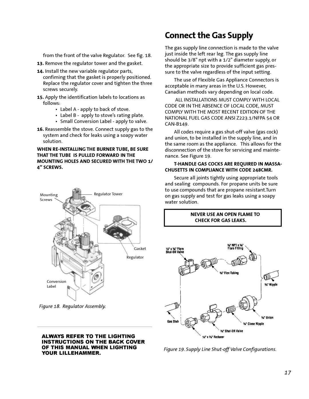
Mounting |
| Regulator Tower |
| ||
Screws |
|
|
Gasket
Regulator
Conversion
Label
Figure 18. Regulator Assembly.
Connect the Gas Supply
The gas supply line connection is made to the valve just inside the left rear leg. The gas supply line should be 3/8" npt with a 1/2" diameter supply, or the appropriate size to provide sufficient gas pres- sure to the valve regardless of the input setting.
The use of Flexible Gas Appliance Connectors is acceptable in many areas in the U.S. However, Canadian methods vary depending on local code.
ALL INSTALLATIONS MUST COMPLY WITH LOCAL CODE OR IN THE ABSENCE OF LOCAL CODE, MUST COMPLY WITH THE MOST RECENT EDITION OF THE NATIONAL FUEL GAS CODE ANSI Z223.1/NFPA 54 OR
All codes require a gas
Secure all joints tightly using appropriate tools and sealing compounds. For propane units be sure to use compounds that are propane resistant.Turn on gas supply and test for gas leaks using a soapy water solution.
NEVER USE AN OPEN FLAME TO
CHECK FOR GAS LEAKS.
ALWAYS REFER TO THE LIGHTING
INSTRUCTIONS ON THE BACK COVER
OF THIS MANUAL WHEN LIGHTING Figure 19. Supply Line
YOUR LILLEHAMMER.
17