~TV/monitor
Composite video cord (supplied)
![]()
Green | Red |
| Blue |
Component video cord (not supplied)
•To select progressive scanning mode (see page 6), use COMPONENT jacks.
•Connect the VIDEO jack,
•You can get better picture quality in the order of— Composite video ]
ŸDigital audio component
OPTICAL
DIGITAL
OUTPUT
Optical digital cord (not supplied)
Protective cap
•Set “DIGITAL AUDIO OUTPUT” in the “AUDIO” menu correctly according to the connected digital audio equipment (see page 39).
•The digital signal through the OPTICAL DIGITAL OUTPUT terminal is transmitted only when the “DVD/CD” is selected as the source.
!Auxiliary equipment
Red
Stereo audio cord (not supplied)
![]() White
White
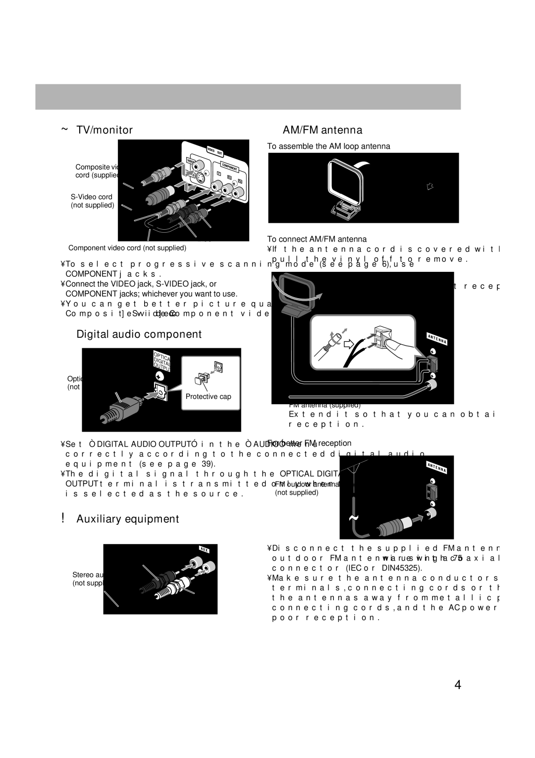
⁄AM/FM antenna
To assemble the AM loop antenna
To connect AM/FM antenna
•If the antenna cord is covered with vinyl on the tip, twist and pull the vinyl off to remove.
AM loop antenna (supplied)
Turn until the best reception is obtained.
FM antenna (supplied)
Extend it so that you can obtain the best reception.
For better FM reception
FM outdoor antenna (not supplied)
•Disconnect the supplied FM antenna, and connect an outdoor FM antenna using a 75 Ω wire with coaxial type connector (IEC or DIN45325).
•Make sure the antenna conductors do not touch any other terminals, connecting cords or the power cord. Also, keep the antennas away from metallic parts of the System, connecting cords, and the AC power cord. This could cause poor reception.
4