Daily Operations / Connections | 6 |
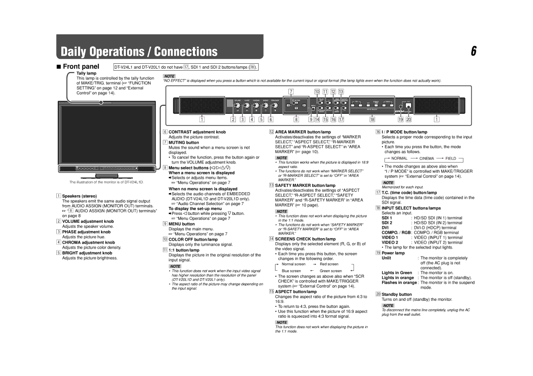
7Front panel
Tally lamp
This lamp is controlled by the tally function | NOTE | |||||||||||||||||||||||||||||||||||||
“NO EFFECT” is displayed when you press a button which is not available for the current input or signal format (the lamp lights even when the function does not actually work). | ||||||||||||||||||||||||||||||||||||||
of MAKE/TRIG. terminal (☞ “FUNCTION | ||||||||||||||||||||||||||||||||||||||
|
|
|
|
|
|
|
|
|
|
|
|
|
|
|
|
|
|
|
|
|
|
|
|
|
|
|
|
|
|
|
|
|
|
|
|
| ||
SETTING” on page 12 and “External |
|
|
|
|
|
|
|
|
|
|
|
|
|
|
|
|
|
|
|
|
|
|
|
|
|
|
|
|
|
|
|
|
|
|
|
|
| |
Control” on page 14). |
|
|
|
|
|
|
|
|
|
|
|
|
|
|
|
|
|
|
|
|
|
|
|
|
|
|
|
|
|
|
|
|
|
|
|
|
| |
|
|
|
|
|
|
|
|
|
|
|
|
|
|
|
|
|
|
|
|
|
|
|
|
|
|
|
|
|
|
|
|
|
|
|
|
|
| |
|
|
|
|
|
|
|
|
|
|
|
|
|
|
|
|
|
|
|
|
|
|
|
|
|
|
|
|
|
|
|
|
|
|
|
|
|
| |
|
|
|
|
|
|
|
|
|
|
|
|
|
|
|
|
|
|
|
|
|
|
|
|
|
|
|
|
|
|
|
|
|
|
|
|
|
| |
|
|
|
|
|
|
|
|
|
|
|
|
|
|
|
|
|
|
|
|
|
|
|
|
|
|
|
|
|
|
|
|
|
|
|
|
|
| |
|
|
|
|
|
|
|
|
|
|
|
|
|
|
|
|
|
|
|
|
|
|
|
|
|
|
|
|
|
|
|
|
|
|
|
|
|
| |
The illustration of the monitor is of
1Speakers (stereo)
The speakers emit the same audio signal output
from AUDIO ASSIGN (MONITOR OUT) terminals.
☞ “8 AUDIO ASSIGN (MONITOR OUT) terminals” on page 8
2VOLUME adjustment knob Adjusts the speaker volume.
3PHASE adjustment knob Adjusts the picture hue.
4CHROMA adjustment knob Adjusts the picture color density.
5BRIGHT adjustment knob Adjusts the picture brightness.
6CONTRAST adjustment knob Adjusts the picture contrast.
7MUTING button
Mutes the sound when a menu screen is not displayed.
•To cancel the function, press the button again or turn the VOLUME adjustment knob.
8Menu select buttons ( ¥ ¥![]() ¥
¥![]() )
)
When a menu screen is displayed
\ Selects or adjusts menu items. ☞ “Menu Operations” on page 7
When no menu screen is displayed
\Selects the audio channels of EMBEDDED AUDIO
☞“Audio Channel Selection” on page 7
To display the
\Press ![]() button while pressing
button while pressing ![]() button.
button.
☞“Menu Operations” on page 7
9MENU button
Displays the main menu.
☞ “Menu Operations” on page 7
pCOLOR OFF button/lamp Displays only the luminance signal.
q1:1 button/lamp
Displays the picture in the original resolution of the input signal.
NOTE
•This function does not work when the input video signal has higher resolution than the resolution of the panel
•The aspect ratio of the picture may change depending on the input signal.
wAREA MARKER button/lamp Activates/deactivates the settings of “MARKER SELECT,” “ASPECT SELECT,”
NOTE
•This function works when the picture is displayed in 16:9 aspect ratio.
•The functions do not work when “MARKER SELECT” or
eSAFETY MARKER button/lamp Activates/deactivates the settings of “ASPECT SELECT,”
NOTE
•This function does not work when displaying the picture in the 1:1 mode.
•The functions do not work when “SAFETY MARKER” or
rSCREENS CHECK button/lamp
Displays only the selected element (R, G, or B) of the video signal.
•Each time you press this button, the screen changes in the following order.
Normal screen | Red screen |
Blue screen | Green screen |
•The screen changes as above also when “SCR CHECK” is controlled with MAKE/TRIGGER system (☞ “External Control” on page 14).
tASPECT button/lamp
Changes the aspect ratio of the picture from 4:3 to 16:9.
•To return to 4:3, press the button again.
•Use this function when the picture of 16:9 aspect ratio is squeezed into 4:3 format signal.
yI / P MODE button/lamp
Selects a proper mode corresponding to the input picture.
•Each time you press the button, the mode changes as follows.
•The mode changes as above also when
“I / P MODE” is controlled with MAKE/TRIGGER system (☞ “External Control” on page 14).
NOTE
Memorized for each input.
uT.C. (time code) button/lamp
Displays the time data (time code) contained in the SDI signal.
iINPUT SELECT buttons/lamps Selects an input.
SDI 1 | : HD/SD SDI (IN 1) terminal |
SDI 2 | : HD/SD SDI (IN 2) terminal |
DVI | : |
COMPO. / RGB: COMPO. / RGB terminal
VIDEO 1 : VIDEO (INPUT 1) terminal
VIDEO 2 : VIDEO (INPUT 2) terminal
• The lamp for the selected input lights.
o Power lamp |
|
Unlit | : The monitor is completely |
| off (the AC plug is not |
| connected). |
Lights in Green | : The monitor is on. |
Lights in orange | : The monitor is off (standby). |
Flashes in orange : The monitor is in the suspend mode.
;Standby button
Turns on and off (standby) the monitor.
NOTE
To disconnect the mains line completely, unplug the AC plug from the wall outlet.
NOTE
This function does not work when displaying the picture in the 1:1 mode.