GR-DVF20
For Customer Use
For clock operation and remote control unit
Dear Customer
It is recommended that you
EN3
Damage Requiring Service
Accessories
Cleaning
Replacement Parts
About Batteries
Battery Pack
EN5
Min DVM-30
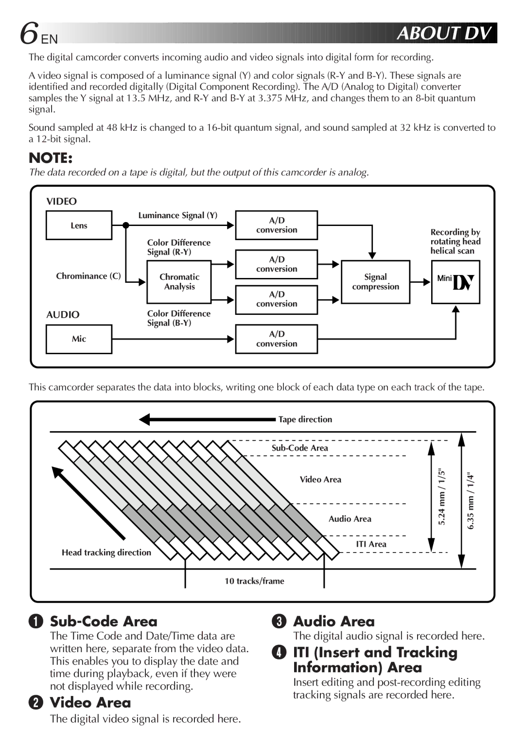
Sub-Code Area
Video Area Audio Area
ITI Insert and Tracking Information Area
Contents
Power
Charging the Battery Pack
Using the Battery Pack
Using AC Power
Using a CAR Battery
Charge Marker
10 EN
Clock Lithium Battery Insertion/Removal
Insert Battery in Holder
RE-INSERT Holder
Date/Time Settings
EN11
12 EN
Loading/Unloading a Cassette
Recording Mode Setting
SET Recording Mode
EN13
Grip Adjustment
Viewfinder Adjustment
14 EN
Shoulder Strap Attachment
Tripod Mounting
EN15
Recording Basic Recording
Power Switch Position
16 EN
Shooting While Watching The Viewfinder
Press Display Button
EN17
Stop Recording
Recording
18 EN
Shooting While Watching The LCD Monitor
Before the following steps, perform pg
Brightness Control
Journalistic Shooting
Interface Shooting
EN19
Basic Recording
Feature Picture Stabilizer
20 EN
Zoom
Battery power
Feature Video Light
To brighten the scene when natural lighting is too dim
EN21
Time Code
Basic Features
When blank portion is recorded on a tape
Recording From The Middle Of a Tape
Select Function
Recording Advanced Features EN23
Displaying The Date And Time During Recording
SET Function Parameters
24 EN
Advanced Features
Snapshot Mode Selection
Snapshot
Motor Drive Mode
EN25
END Setting
Using Menu For Detailed Adjustment
Make Setting
Select Function Parameters in DATE/TIME Menu or System Menu
Factory-preset
EN27
Recording Menu Explanations
Date/Time Menu Explanations
System Menu Explanations
Effect Selection
Fade/Wipe Effects
EN29
FADE/WIPE Selection
Before the following steps, perform steps 1 through 3 on pg
30 EN
Picture Wipe or Dissolve Selection P, P, P, P , P, P and P
If you select Picture Wipe/Dissolve during recording
EN31
Fader And Wipe Menu
Menu Effect
Disable Mode
Recording Advanced Features
Select Mode
32 EN
Slow Slow Shutter
EN33
34 EN
Focusing
When shooting a scene with a high-contrast background
Auto Focus
EN35
Manual Focus
Exposure Control
Access Exposure Control
36 EN
To darken the image
Center SUBJECT, Lock Iris
Iris Lock
EN37
Iris
38 EN
White Balance Adjustment
Accessment White Balance Adjust
To Return To Automatic White Balance
EN39
Enter Setting
Manual White Balance Operation
Exit Manual White Balance AD- Justment
Playback Basic Playback
Speaker Volume Control
40 EN
Rewind or Fast-forward the tape
Feature Slow-Motion Playback
Feature Still Playback
Feature Shuttle Search
Feature Playback Zoom
42 EN
Playback Advanced Features
Access Playback Menu
Playback Menu
EN43
Playback Sound
Displaying the Date During Playback
Displaying The Time Code During Playback
Connectors
44 EN
Connections
Connectvcr Camcorder to TV or
Connectinput VCR Output to TV Supply Power
EN45
Turn on the camcorder, the VCR and the TV
46 EN
Tape Dubbing
Installing The Battery
EN47
48 EN
Functions
Buttons
EN49
To allow slow-speed search in either direction
To stop Slow-Motion Playback in progess, press Play
END Zoom
Playback Zoom
Activate Zoom
Down
EN51
Accessmenu Playback Effect Select
Playback Special Effects
Start Playback
SET REMOTE/VCR Code
52 EN
Random Assemble Editing R.A.Edit
Operate VCR
EN53
Jlip
USE FADE/WIPE on Scene Transition if Necessary
54 EN
Select Scenes
USE Program AE with Special Effects if Necessary
Prepare Source Tape
EN55
Automatic Editing to VCR
Stop Editing
56 EN
For More Accurate Editing
Diagnosing VCR’S Against Camcorder Timing
Adjustment of VCR’S Against Camcorder Timing
EN57
Input Correction Data
58 EN
Corrective Action
Selected the mode For editing was registered
Video mode Video playback
Set the Power Switch to Effects and Fade/Wipe
Completed pg Being used in a scene
60 EN
Recording Menu Use the Picture Wipe Function pg
Whitish
Indicators On Screen is set to Set on Screen to on
OFF in the Date/Time Date/Time Menu Screen
Become hot
62 EN
Open the lens cover pg Close the LCD monitor
Clean Lens
Clean Exterior
Clean LCD Monitor
After Use
64EN
# $ y %
Controls
Connectors
Indicators
Other Parts
LCD Monitor/Viewfinder Indications During Recording
66 EN
Indications
Function
LCD Monitor/Viewfinder Indications During Playback
EN67
Indications Function
68 EN
To avoid hazard
To prevent damage and prolong service life
EN69
During use
To prolong service life
For safety, do not
Avoid using the unit
To prevent damage to the LCD monitor, do not
Camcorder
AC Power Adapter/Charger AA-V15U
Connectors
EN71
GR-DVF20

 DV
DV