2. CONTROLS, INDICATORS AND CONNECTORS
2-3 Left Side Section
PUSH
FRONT |
AUDIO IN |
LINE OUT
LENS | |
Y/C OUT | MONITOR OUT |
|
r
e w q
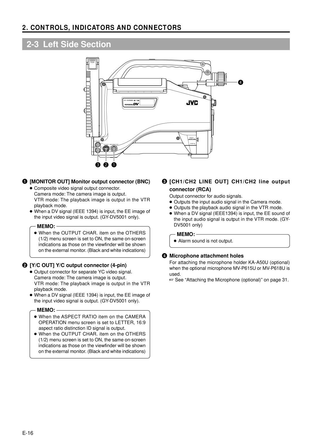
1[MONITOR OUT] Monitor output connector (BNC)
●Composite video signal output connector. Camera mode: The camera image is output.
VTR mode: The playback image is output in the VTR playback mode.
●When a DV signal (IEEE 1394) is input, the EE image of the input video signal is output.
MEMO:
●When the OUTPUT CHAR. item on the OTHERS (1/2) menu screen is set to ON, the same
3[CH1/CH2 LINE OUT] CH1/CH2 line output connector (RCA)
Output connector for audio signals.
●Outputs the input audio signal in the Camera mode.
●Outputs the playback audio signal in the VTR mode.
●When a DV signal (IEEE1394) is input, the EE sound of the input audio signal is output in the VTR mode. (GY- DV5001 only)
MEMO:
●Alarm sound is not output.
2[Y/C OUT] Y/C output connector (4-pin)
●Output connector for separate YC video signal. Camera mode: The camera image is output.
VTR mode: The playback image is output in the VTR playback mode.
●When a DV signal (IEEE 1394) is input, the EE image of the input video signal is output.
4Microphone attachment holes
For attaching the microphone holder
☞ See “Attaching the Microphone (optional)” on page 31.
MEMO:
●When the ASPECT RATIO item on the CAMERA OPERATION menu screen is set to LETTER, 16:9 aspect ratio distinction ID signal is output.
●When the OUTPUT CHAR. item on the OTHERS (1/2) menu screen is set to ON, the same