Connectors
4.7In-Circuit-Programming Connector (X12)
There is a
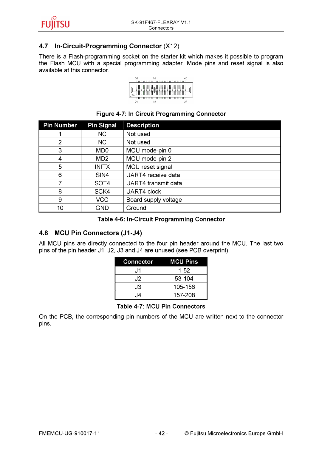
Figure 4-7: In Circuit Programming Connector
Pin Number | Pin Signal | Description |
1 | NC | Not used |
2 | NC | Not used |
3 | MD0 | MCU |
4 | MD2 | MCU |
5 | INITX | MCU reset signal |
6 | SIN4 | UART4 receive data |
7 | SOT4 | UART4 transmit data |
8 | SCK4 | UART4 clock |
9 | VCC | Board supply voltage |
10 | GND | Ground |
Table 4-6: In-Circuit Programming Connector
4.8MCU Pin Connectors (J1-J4)
All MCU pins are directly connected to the four pin header around the MCU. The last two pins of the pin header J1, J2, J3 and J4 are unused (see PCB overprint).
Connector | MCU Pins |
J1 | |
J2 | |
J3 | |
J4 |
Table 4-7: MCU Pin Connectors
On the PCB, the corresponding pin numbers of the MCU are written next to the connector pins.
- 42 - | © Fujitsu Microelectronics Europe GmbH |