Contents
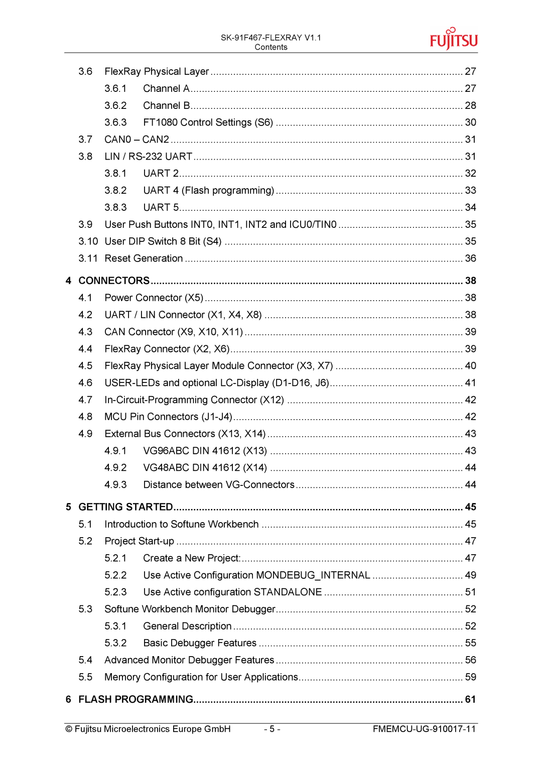
3.6 | FlexRay Physical Layer | 27 | |
| 3.6.1 | Channel A | 27 |
| 3.6.2 | Channel B | 28 |
| 3.6.3 FT1080 Control Settings (S6) | 30 | |
3.7 | CAN0 – CAN2 | 31 | |
3.8 | LIN / | 31 | |
| 3.8.1 | UART 2 | 32 |
| 3.8.2 UART 4 (Flash programming) | 33 | |
| 3.8.3 | UART 5 | 34 |
3.9 | User Push Buttons INT0, INT1, INT2 and ICU0/TIN0 | 35 | |
3.10 | User DIP Switch 8 Bit (S4) | 35 | |
3.11 | Reset Generation | 36 | |
4 CONNECTORS | 38 | ||
4.1 | Power Connector (X5) | 38 | |
4.2 | UART / LIN Connector (X1, X4, X8) | 38 | |
4.3 | CAN Connector (X9, X10, X11) | 39 | |
4.4 | FlexRay Connector (X2, X6) | 39 | |
4.5 | FlexRay Physical Layer Module Connector (X3, X7) | 40 | |
4.6 | 41 | ||
4.7 | 42 | ||
4.8 | MCU Pin Connectors | 42 | |
4.9 | External Bus Connectors (X13, X14) | 43 | |
| 4.9.1 VG96ABC DIN 41612 (X13) | 43 | |
| 4.9.2 VG48ABC DIN 41612 (X14) | 44 | |
| 4.9.3 | Distance between | 44 |
5 GETTING STARTED | 45 | ||
5.1 | Introduction to Softune Workbench | 45 | |
5.2 | Project | 47 | |
| 5.2.1 Create a New Project: | 47 | |
| 5.2.2 Use Active Configuration MONDEBUG_INTERNAL | 49 | |
| 5.2.3 Use Active configuration STANDALONE | 51 | |
5.3 | Softune Workbench Monitor Debugger | 52 | |
| 5.3.1 | General Description | 52 |
| 5.3.2 | Basic Debugger Features | 55 |
5.4 | Advanced Monitor Debugger Features | 56 | |
5.5 | Memory Configuration for User Applications | 59 | |
6 FLASH PROGRAMMING | 61 | ||
© Fujitsu Microelectronics Europe GmbH | - 5 - |
