English
AV COMPU LINK Remote Control System
The AV COMPU LINK remote control system allows you to operate JVC’s video components (TV and VCR) through the unit.
This unit is equipped with the AV COMPU
• Refer also to the manuals supplied with your video components.
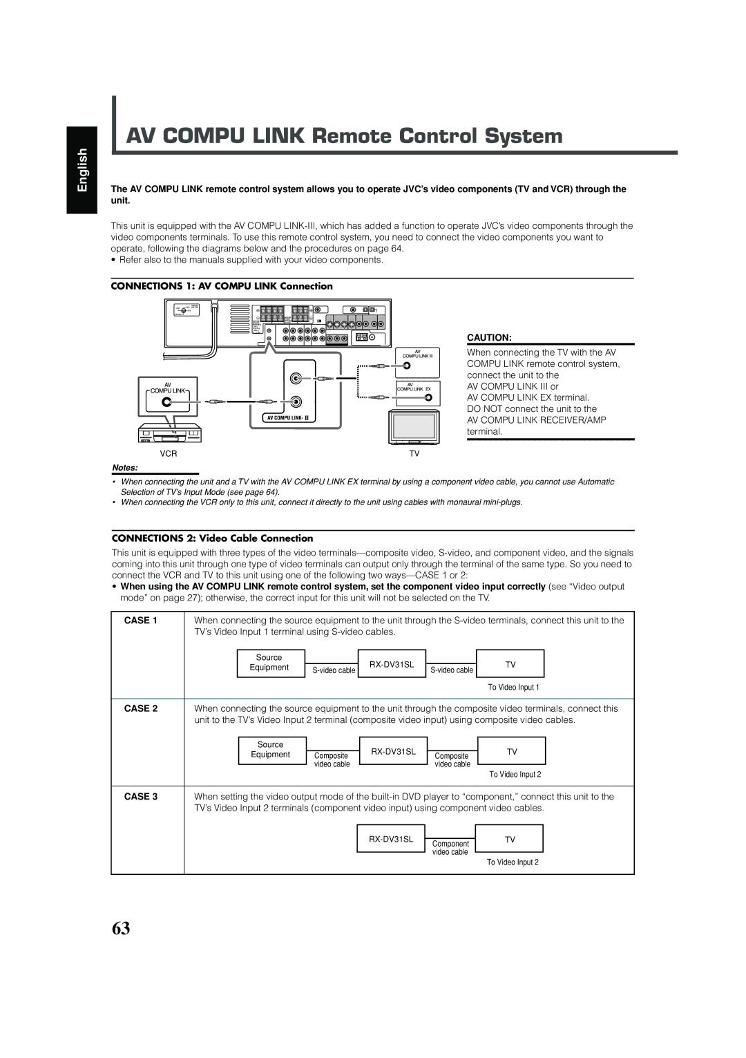
CONNECTIONS 1: AV COMPU LINK Connection
|
| VOLTAGE |
|
|
|
220V | 110V | SELECTOR |
|
|
|
| 127V |
|
|
|
|
|
|
|
|
| |
|
|
|
| CAUTION: | |
|
|
|
| SPEAKER | |
|
| CAUTION: | IMPEDANCE | ||
|
| SPEAKER | 8 | 16 | |
|
| IMPEDANCE |
|
| |
|
| 1 OR 2: |
|
| |
|
| 8 | 16 |
|
|
|
| 1 AND 2: |
|
| |
|
| 16 | 32 |
|
|
CAUTION:
When connecting the TV with the AV COMPU LINK remote control system, connect the unit to the
AV COMPU LINK III or
AV COMPU LINK EX terminal. DO NOT connect the unit to the
AV COMPU LINK RECEIVER/AMP terminal.
VCR | TV |
Notes:
•When connecting the unit and a TV with the AV COMPU LINK EX terminal by using a component video cable, you cannot use Automatic Selection of TV’s Input Mode (see page 64).
•When connecting the VCR only to this unit, connect it directly to the unit using cables with monaural
CONNECTIONS 2: Video Cable Connection
This unit is equipped with three types of the video
•When using the AV COMPU LINK remote control system, set the component video input correctly (see “Video output mode” on page 27); otherwise, the correct input for this unit will not be selected on the TV.
CASE 1 | When connecting the source equipment to the unit through the | |||||||
| TV’s Video Input 1 terminal using |
|
|
|
| |||
|
|
|
|
|
|
|
|
|
|
| Source |
|
|
| TV |
| |
|
| Equipment |
| |||||
|
|
|
|
| ||||
|
|
|
|
|
| |||
|
|
|
|
|
|
|
|
|
|
|
|
|
|
|
| To Video Input 1 | |
|
|
|
|
|
|
|
|
|
CASE 2 | When connecting the source equipment to the unit through the composite video terminals, connect this | |||||||
| unit to the TV’s Video Input 2 terminal (composite video input) using composite video cables. | |||||||
|
|
|
|
|
|
|
|
|
|
| Source |
|
|
| TV |
| |
|
| Equipment | Composite | Composite |
| |||
|
|
|
|
| ||||
|
|
| video cable |
| video cable |
|
| |
|
|
|
| To Video Input 2 | ||||
|
|
|
|
|
|
| ||
|
|
|
|
|
|
|
|
|
CASE 3 | When setting the video output mode of the | |||||||
| TV’s Video Input 2 terminals (component video input) using component video cables. | |||||||
|
|
|
|
|
|
|
|
|
|
|
|
|
|
| TV |
| |
|
|
|
| Component |
|
| ||
|
|
|
|
|
|
|
| |
|
|
|
|
| video cable |
|
|
|
|
|
|
|
|
| To Video Input 2 | ||
|
|
|
|
|
|
| ||
|
|
|
|
|
|
|
|
|
63