Parts Identification
English
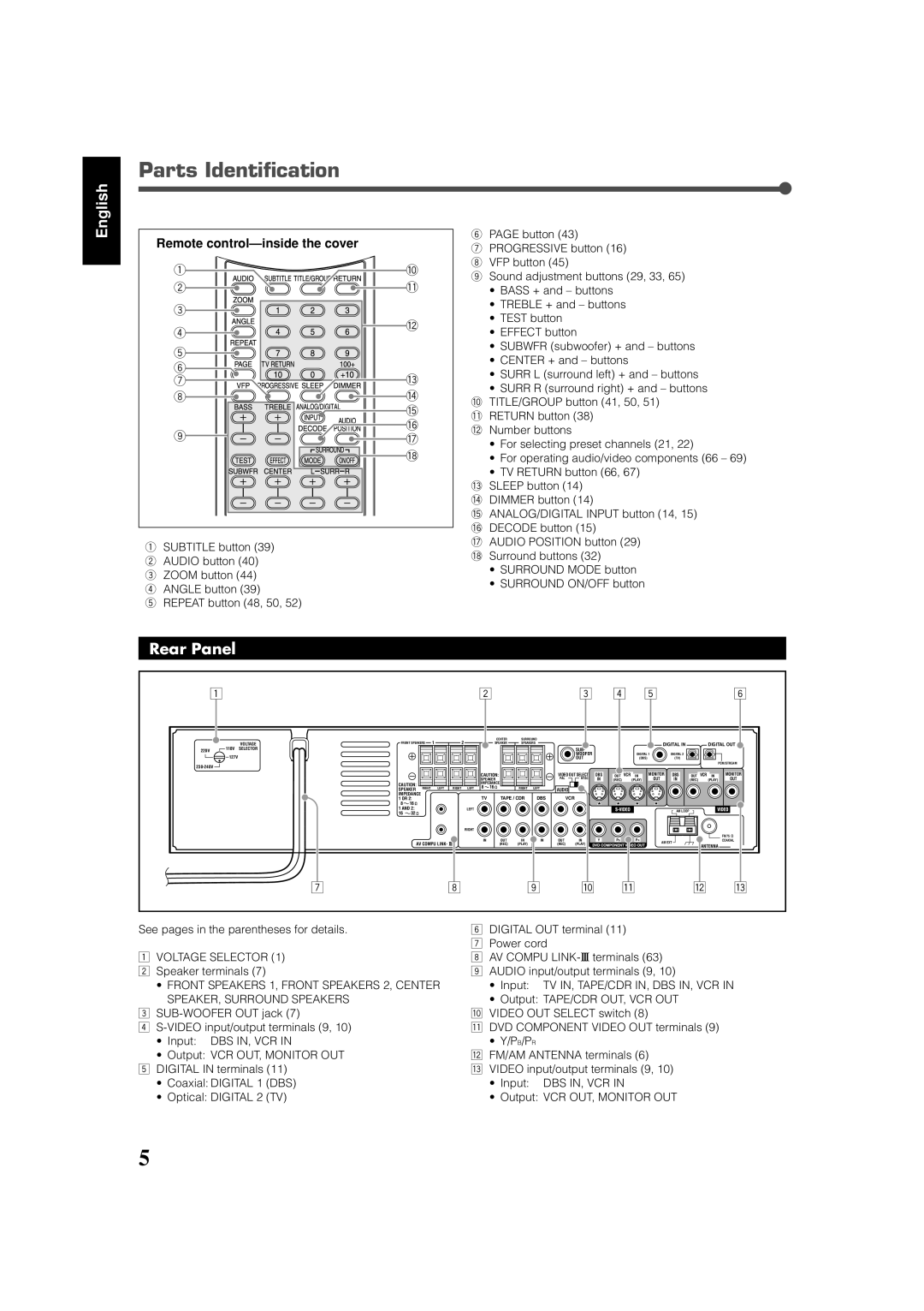
Remote control—inside the cover
1 | 0 | |
2 | - | |
3 |
| |
4 | = | |
| ||
5 |
| |
6 |
| |
7 | ~ | |
8 | ! | |
| @ | |
9 | # | |
$ | ||
| ||
| % |
1SUBTITLE button (39)
2 AUDIO button (40)
3 ZOOM button (44)
4 ANGLE button (39)
5 REPEAT button (48, 50, 52)
6PAGE button (43)
7PROGRESSIVE button (16)
8 VFP button (45)
9 Sound adjustment buttons (29, 33, 65)
•BASS + and – buttons
•TREBLE + and – buttons
•TEST button
•EFFECT button
•SUBWFR (subwoofer) + and – buttons
•CENTER + and – buttons
•SURR L (surround left) + and – buttons
•SURR R (surround right) + and – buttons 0 TITLE/GROUP button (41, 50, 51)
- RETURN button (38) = Number buttons
•For selecting preset channels (21, 22)
•For operating audio/video components (66 – 69)
•TV RETURN button (66, 67)
~SLEEP button (14) ! DIMMER button (14)
@ ANALOG/DIGITAL INPUT button (14, 15)
# DECODE button (15)
$ AUDIO POSITION button (29) % Surround buttons (32)
•SURROUND MODE button
•SURROUND ON/OFF button
Rear Panel
1 |
|
|
|
|
|
|
|
| 2 |
|
|
| 3 |
| 4 |
| 5 |
|
|
|
| 6 | ||
|
|
| FRONT SPEAKERS | 1 |
| 2 |
| CENTER | SURROUND |
|
|
|
|
|
|
|
|
|
|
|
| |||
|
| VOLTAGE |
|
| SPEAKER | SPEAKERS |
|
|
|
|
|
| DIGITAL IN |
|
| DIGITAL OUT | ||||||||
220V | 110V | SELECTOR |
|
|
|
|
|
|
|
|
|
|
| SUB- |
|
|
| DIGITAL 1 | DIGITAL 2 |
|
|
|
| |
| 127V |
|
|
|
|
|
|
|
|
|
|
|
| WOOFER |
|
|
|
|
|
|
| |||
|
|
|
|
|
|
|
|
|
|
|
|
| OUT |
|
|
| (DBS) | (TV) |
|
|
|
| ||
|
|
|
|
|
|
|
|
|
|
|
|
|
|
|
|
|
|
|
|
|
|
| PCM/STREAM | |
|
|
|
|
|
|
|
|
|
|
|
|
|
|
|
|
|
|
|
|
|
|
|
| |
|
|
|
|
|
|
|
|
| CAUTION: |
|
| VIDEO OUT SELECT | DBS | OUT | VCR | IN | MONITOR | DBS | OUT | VCR | IN | MONITOR | ||
|
|
|
|
|
|
|
|
| SPEAKER |
|
| PAL | NTSC | IN | (REC) |
| (PLAY) | OUT | IN | (REC) |
| (PLAY) | OUT | |
|
|
| CAUTION: |
|
|
|
| IMPEDANCE |
|
|
|
|
|
|
|
|
|
|
|
|
|
| ||
|
|
| RIGHT | LEFT | RIGHT | LEFT | 8 | 16 | RIGHT | LEFT |
|
|
|
|
|
|
|
|
|
|
|
| ||
|
|
| SPEAKER | AUDIO |
|
|
|
|
|
|
|
|
|
| ||||||||||
|
|
| IMPEDANCE |
|
|
|
| TV | TAPE / CDR | DBS |
| VCR |
|
|
|
|
|
|
|
|
|
| ||
|
|
| 1 OR 2: |
|
|
|
|
|
|
|
|
|
|
|
|
|
|
| ||||||
|
|
| 8 | 16 |
|
|
|
|
|
|
|
|
|
|
|
|
|
|
|
|
|
|
|
|
|
|
| 1 AND 2: |
|
|
| LEFT |
|
|
|
|
|
|
|
|
|
|
| AM LOOP |
|
|
|
| |
|
|
| 16 | 32 |
|
|
|
|
|
|
|
|
|
|
|
|
|
|
|
|
|
|
| |
|
|
|
|
|
|
|
|
|
|
|
|
|
|
|
|
|
|
|
|
|
|
| ||
|
|
|
|
|
|
|
| RIGHT |
|
|
|
|
|
|
|
|
|
|
|
|
|
|
|
|
|
|
|
|
|
|
|
|
| IN | OUT | IN | IN | OUT | IN | Y | PB |
| PR |
|
|
|
|
| FM 75 |
|
|
|
| AV COMPU LINK- |
|
|
| AM EXT |
|
|
| COAXIAL | ||||||||||||
|
|
|
|
|
|
| (REC) | (PLAY) |
| (REC) | (PLAY) |
|
|
|
|
| ANTENNA |
| ||||||
|
|
|
|
|
|
|
|
|
|
|
|
|
|
|
|
|
|
|
|
|
|
| ||
|
|
| 7 |
|
|
| 8 |
|
|
| 9 |
| p |
|
| q |
|
| w |
| e | |||
See pages in the parentheses for details. | 6 | DIGITAL OUT terminal (11) | ||
|
| 7 | Power cord | |
1 | VOLTAGE SELECTOR (1) | 8 | AV COMPU LINK- terminals (63) | |
2 | Speaker terminals (7) | 9 | AUDIO input/output terminals (9, 10) | |
| • FRONT SPEAKERS 1, FRONT SPEAKERS 2, CENTER |
| • Input: | TV IN, TAPE/CDR IN, DBS IN, VCR IN |
| SPEAKER, SURROUND SPEAKERS |
| • Output: TAPE/CDR OUT, VCR OUT | |
3 | p VIDEO OUT SELECT switch (8) | |||
4 | q DVD COMPONENT VIDEO OUT terminals (9) | |||
| • Input: DBS IN, VCR IN |
| • Y/PB/PR |
|
| • Output: VCR OUT, MONITOR OUT | w FM/AM ANTENNA terminals (6) | ||
5 | DIGITAL IN terminals (11) | e VIDEO input/output terminals (9, 10) | ||
| • Coaxial: DIGITAL 1 (DBS) |
| • Input: | DBS IN, VCR IN |
| • Optical: DIGITAL 2 (TV) |
| • Output: VCR OUT, MONITOR OUT | |
5