RX-DV5SL
Mises en garde, précautions et indications diverses
English Français
Table of Contents
Front Panel
Adjust button 23
Parts Identification
Display
Remote Control
Parts Identification
Getting Started
Before Installation Putting Batteries in the Remote Control
Checking the Supplied Accessories
AM antenna connection
Connecting the FM and AM Antennas
Getting Started
FM antenna connection
Connecting the front, center, and rear speakers
Connecting the Speakers
Connecting the subwoofer speaker
Speaker Layout Diagram
For video connections
Connecting Audio/Video Components
About connecting cords
For audio connections
Green
Video connections
Audio connections
White
VCR
VCR connection
DBS tuner connection
White
CD recorder
Cassette deck/CD recorder connection
Digital connection
Basic Operations
Turn On the Power
Adjust the Volume
Select the Source to Play
Turning Off the Power With the Sleep Timer
Changing the Source Name
When DVD is selected as the source, you can also
Input mode
On the remote control
Basic Operations
Activating the Recording Mode
Attenuating the Input Signal
Changing the Scanning Mode
Input ATT indicator
Load a Disc
Basic DVD Player Operations
Open the Disc Tray
Start Playback
Activate Realistic Sound Field
Select Surround Mode
Turn Off the Power into Standby
Stop Playback
Tuning into Stations Manually Using Preset Tuning
Tuner Operations
Selecting the FM Reception Mode
Operation Buttons
Basic Settings
Operating Procedure
¶ For subwoofer
YES
Low frequency effect attenuator-LFE
Basic Settings
Set the appropriate digital terminal setting
Digital input Digital in terminals-DGT
On the display
AV Compu Link Remote Control System on pages 59
Auto surround-AUTO SR Video output mode-VOUT
Set the output terminal appropriately
Press Control 3 or 2 to adjust Front speaker balance
Sound Adjustments
Press Adjust
Adjustment items
Tone-BASS and Treble
Adjusting sound from the remote control
Front speaker output balance -BAL balance
DAP effect level-EFFECT
DTS Digital Surround
Creating Realistic Sound Fields
Dolby Surround
DAP Digital Acoustic Processor modes
Possible × Impossible
All Channel Stereo
Reflections from behind Early reflections Direct sounds
Selecting Surround Modes
Activating Surround Mode
Creating Realistic Sound Fields
Adjust the speaker output levels as follows
Adjusting Surround Mode Using Remote Control
Adjust the sound
For using test tone
Playable Disc Types
DVD Player Operations
Disc Information
Discs you can play Disc Type
Menu-driven playback
Disc structure
Playback Control function PBC
DVD Player Operations
Using the On-screen Bar
Contents of the on-screen bar with the pull-down menu
Press on Screen twice
Basic Operation through the On-screen Bar
Changing the Time Indication
Press Enter
From the DVD menu
Locating a Desired Scene from Disc Menu
Press TOP Menu or Menu
From the VCD/SVCD menu with PBC
Press Angle repeatedly to select the desired view angle
Selecting a View Angle-ANGLE
Press Angle
Press and hold Angle for a few seconds
Press Audio
Changing the Languages-SUBTITLE
Press Subtitle
Press Audio repeatedly to select the desired audio language
For VCD
Press Audio repeatedly to select the desired audio channel
Selecting the audio channel
For Svcd
Locating a desired chapter/track Chapter/Track Search
Playing from a Specified Position on a Disc
Use the number buttons 0-9 to enter the time
Locating a desired position-Time Search
Locating a desired scene-DIGEST
Press Digest
Press cursor 5/∞/3/2 to move to the desired scene
Special Picture Playback
Changing the VFP setting-VFP
Press cursor 3 or 2 repeatedly to select VFP mode
Repeat steps 2 to 4 to adjust other parameters
To adjust the appearance of the picture
Playing back in the desired order
Program Playback and Random Playback
Repeat to program the next steps
Playing back tracks in random order
Repeating a desired part
Repeat Playback
Repeating a current title, group, chapter, or All tracks
Special Playback for DVD Audio
Activating Surround mode
Additional Information for DVD Audio
About indication on the front panel
Selecting a still picture
Press cursor ∞ or 5 repeatedly to select the desired
Press the number buttons to select a bonus group
Playing back a bonus group
Load an MP3 disc, then press
MP3 Disc Playback
Basic Operations
Operations through the MP3 Control Screen
Press Repeat
Load a Jpeg disc, then press
Jpeg Disc Playback
Slide-show Playback
Operations through the Jpeg Control Screen
Press Menu or
Operation Buttons Configuration of Choice Menu
Choice Menu Operations
Press cursor 3 or 2 repeatedly To display Picture menu
Press Enter to finish the setting
Press Choice
Press cursor ∞ or 5 repeatedly To move to Progressive
Picture menu
Choice Menu Operations
Language menu
Jpeg
Audio menu
MP3
MAX
SPK. Setting menu
Others menu
Select this to deactivate it
Setting Parental Lock
Restricting Playback by Parental Lock
Releasing Parental Lock temporarily
Changing the setting of Parental Lock
New setting is stored
Country/Area codes list for Parental Lock
Glossary for DVD Player
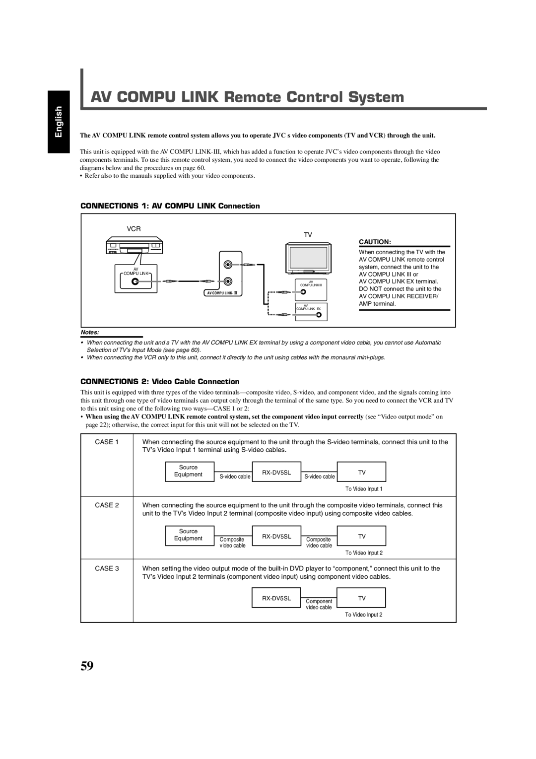
Connections 1 AV Compu Link Connection
AV Compu Link Remote Control System
TV’s Video Input 1 terminal using S-video cables
Connections 2 Video Cable Connection
Automatic Power On/Off
Remote Control of the TV and VCR Using This Remote Control
Automatic Selection of TV’s Input Mode
One-Touch Video Play
CD recorder
Operating JVC’s Audio/Video Components
Operating Audio Components
Sound control section Amplifier
REW
Operating Video Components
STANDBY/ON VCR
TV/VIDEO
Release STANDBY/ON TV
Changing the Preset Signal Codes
Operating Other Manufacturers’ Equipment
Try to operate your TV by pressing
Press DBS
Enter the manufacturer’s code using the number buttons 1-9
Press and hold
Release STANDBY/ON DBS
Enter the manufacturer’s code
Using the number buttons 1-9, 0. Test
Operating Other Manufacturers’ Equipment
Release STANDBY/ON VCR
Cleaning the Unit
Maintenance
Cleaning Discs
General Notes
Troubleshooting
Genaral
For DVD Player
For MP3
Troubleshooting
For Tuner
For Jpeg
FM tuner IHF
Specifications
Amplifier
AM tuner
Victor Company of JAPAN, Limited 0802NHMMDWJEM