SP-WA75
Consists of XV-THA75, SP-WA75, SP-XSA75, and SP-XCA75
LVT0958-010A
XV-THA75
Class 1 Laser Product
Important for Laser Products
Page
Table of contents
Introduction
Precautions
Checking the supplied accessories
Safety precautions
DIGITAL, Digital EX , DTS
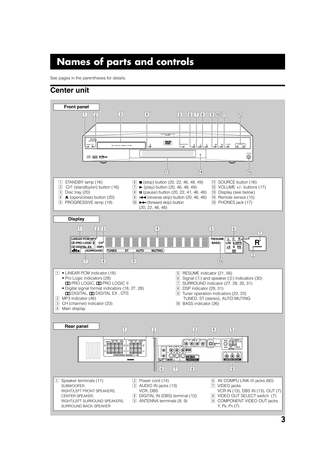
Names of parts and controls
Center unit
PRO LOGIC, PRO Logic
Names of parts and controls
Remote control
Source selecting buttons 16 VCR/DBS, FM/AM, DVD
Video Region Code Type Logo Format Number
About discs
Playable disc types
Discs you can play
Before playing a disc, make sure of the following
About discs
Disc structure
Playback Control function PBC Only for VCD and Svcd
Connections
Connecting a TV
Connecting a TV
Getting started
Getting started
Connecting the AM and FM antennas
AM loop antenna
FM antenna
Connecting the supplied FM antenna If reception is poor
Inserting the speaker cord into the speaker terminals
Connecting the satellite speakers and subwoofer
Speaker layout diagram
Before connecting the speaker cord
Subwoofer Surround back Speaker
Location of attachment to the wall
Installing the satellite speakers on the wall
VCR connection
Connecting video components
DBS tuner connection
Plug into AC outlet Power cord
Connecting the power cord
Replace the cover
Using the remote control
Putting batteries in the remote control
Operating the system using the remote control
Press Source repeatedly
Basic operations
Selecting the source to play
Turning on the system
Listening with headphones
Adjusting the volume
Adjusting the output level of subwoofer
Adjusting the brightness
Press Sleep
Turning off the power with the sleep timer
Changing the analog/digital input mode and decoding mode
Basic operations
About scanning system
Storing basic adjustments- auto memory
Changing the scanning mode
Press and hold Progressive for 5 seconds
Basic DVD player operations
Resume playback function see
About the indications on the display
Preventing screen burn-out-screen saver function
To store the preset stations
Setting the AM tuner interval spacing
Tuning in to stations manually
Using preset tuning
To tune in to a preset station
Selecting the FM reception mode
Reducing the noise of AM broadcast
Press SETTING/ADJUST once
Basic settings
Operating procedure
Setting speaker sizes
Setting the crossover frequency-CROSS
Setting the speaker distance
Setting the phase of subwoofer
Setting the video output for DVD
Audio adjustments
Dolby Digital
Creating realistic sound fields
Surround modes
Dolby Digital EX
Creating realistic sound fields
DAP Digital Acoustic Processor modes
DSP modes
All Channel Stereo
Speaker and signal indicators
Using DSP mode
Using Surround mode
After adjusting sound
Adjusting sound
Adjust the speaker output levels -10 dB to +10 dB
10 keys are activated for sound adjustments
Press on Screen
Using the on-screen bar
DVD player operations
Showing the on-screen bar
Changing the time information
DVD player operations
Basic operation through the on-screen bar
Press TOP Menu or Menu
Locating a particular scene from the DVD menu
PBC
Selecting a view angle
Selecting a view angle
Showing all view angles on the TV
Press Subtitle
Changing the subtitle and audio languages
Selecting the subtitle language
Selecting the audio language
For VCD
Selecting the audio channel
Press Audio or Cursor ∞/5 repeatedly to
Select the desired audio language Press Audio
Press the number buttons 0-9 to enter the specified time
Playing from a particular position
Locating a particular chapter Chapter search
Locating a particular position Time search
Press Cursor 3/2/∞/5 to move to the desired scene
Locating a particular scene
Press Digest
Frame-by-frame playback
Special picture playback
Showing continuous still pictures
Press Zoom + to zoom in or Zoom to zoom out
Playing back in slow-motion
Zooming in and out
Press ¡ or
Repeat steps 2-4to adjust other parameters
Changing the VFP setting
Press Cursor 3/2 repeatedly to select the VFP mode
To adjust the appearance of picture
Press Play
Repeat to program other tracks
Repeating a particular portion
Press Cursor ∞/5 repeatedly to select repeat play mode
Repeat play
Repeating title, chapter, or tracks
Load an MP3 disc, then press Play
MP3 disc playback
Basic operation
To start playback
To start playback from the specified track number
Operating through the MP3 Control screen
MP3 Control screen
Operations
Load an Jpeg disc, then press Play
Jpeg disc playback
Slide-show
To start slide-show playback
Jpeg Control screen
Operating through the Jpeg Control screen
Enter
Using the choice menus
Choice menus
Choice
To set other items on the same choice menu
Basic operating procedure
Press Choice
Press Cursor ∞/5 repeatedly to move to Screen Saver
Select one of the languages-ENGLISH, Chinese or
Using the choice menus
Language codes list
Language menu
Turn on or OFF the screen saver function
Picture menu
Multi Normal 169 Multi Auto 43 Multi LB Multi PS
You can activate or deactivate the screen saver function
Audio menu
Using the choice menu
To be on the Next
SPK. Setting menu
Test Tone
SUB Woofer
¶ Cross Over
Others menu
Restricting playback-Parental Lock
Setting Parental Lock
To exit from the choice menu
Releasing Parental Lock temporarily
Changing the setting of Parental Lock
Press the number buttons 0-9 to enter your password
New setting is stored
Country/area codes list for Parental Lock
Connection 1 AV Compu Link connection
AV Compu Link remote control system
Connection 2 Video cord connection
Available functions
Procedure for connection
Channel +
Operating TV
Release TV Try to operate your TV by pressing TV
TV/VIDEO
CATV/DBS
Operating Catv converter or DBS tuner
Manufacturers’ codes for Catv converter or DBS tuner Code
Press and hold VCR
Set the remote control mode selector to
Operating other manufacturers’ video equipment
Operating VCR
To clean the disc
Maintenance
Stains on the system
General
Troubleshooting
DVD Playback
MP3 Playback Jpeg Playback
Troubleshooting
See Titles and chapters
Glossary
Specifications
Page
2002 Victor Company of JAPAN, Limited 1102TMMMDWJEM

 PRO LOGIC,
  PRO LOGIC II
 DIGITAL,
  DIGITAL EX , DTS