Installation and Connection
Cable Connection
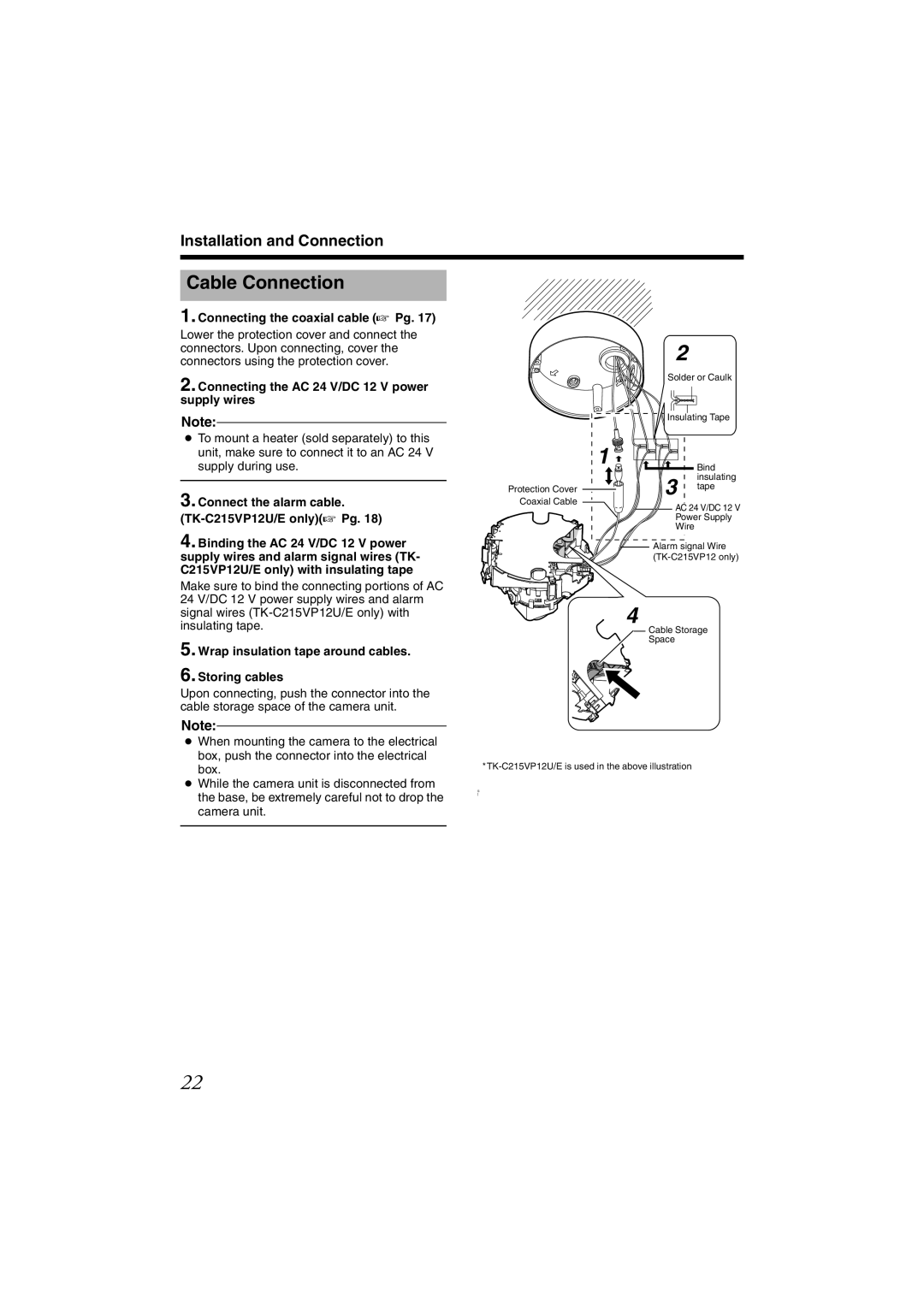
1. Connecting the coaxial cable (A Pg. 17)
Lower the protection cover and connect the connectors. Upon connecting, cover the connectors using the protection cover.
2. Connecting the AC 24 V/DC 12 V power supply wires
2
Solder or Caulk
Note:
●To mount a heater (sold separately) to this unit, make sure to connect it to an AC 24 V supply during use.
3. Connect the alarm cable. (TK-C215VP12U/E only)(A Pg. 18)
4. Binding the AC 24 V/DC 12 V power supply wires and alarm signal wires (TK- C215VP12U/E only) with insulating tape
Make sure to bind the connecting portions of AC 24 V/DC 12 V power supply wires and alarm signal wires
5. Wrap insulation tape around cables.
6. Storing cables
Upon connecting, push the connector into the cable storage space of the camera unit.
Note:
Protection Cover Coaxial Cable
Insulating Tape | |
1 | Bind |
| |
3 | insulating |
tape | |
AC 24 V/DC 12 V | |
Power Supply | |
Wire |
|
Alarm signal Wire
4
Cable Storage
Space
●When mounting the camera to the electrical box, push the connector into the electrical box.
●While the camera unit is disconnected from the base, be extremely careful not to drop the camera unit.
S
]
22