Digital Connections
Before proceeding, check whether the optical digital cable can be connected.
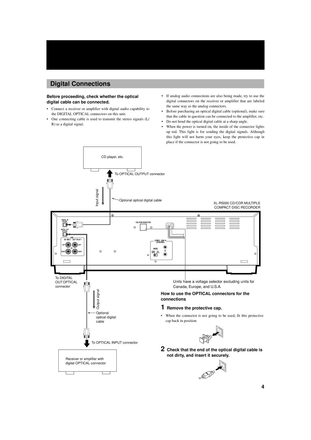
•Connect a receiver or amplifier with digital audio capability to the DIGITAL OPTICAL connectors on this unit.
•One connecting cable is used to transmit the stereo signals (L/
R)as a digital signal.
•If analog audio connections are also being made, try to use the digital connectors on the receiver or amplifier that are labeled the same way as the analog connectors.
•Before purchasing an optical digital cable (optional), make sure that the cable in question can be connected to the amplifier, etc.
•Do not bend the optical digital cable at a sharp angle.
•When the power is turned on, the inside of the connector lights up red. This light is for sending the digital signals. Although this light will not harm your eyes, keep the protective cap in place if the connector is not going to be used.
Input signal
DIGITAL IN |
|
OPTICAL |
|
DIGITAL OUT |
|
OPTICAL |
|
LINE |
|
IN ( REC) OUT (PLAY ) | |
LEFT | LEFT |
RIGHT | RIGHT |
To DIGITAL |
|
OUT OPTICAL |
|
connector |
|
![]() Output signal
Output signal
CD player, etc.
To OPTICAL OUTPUT connector
![]() Optional optical digital cable
Optional optical digital cable
XL-R5000 CD/CDR MULTIPLE
COMPACT DISC RECORDER
VOLTAGE SELECTOR
COMPU | ||
| (SYNCHRO) | |
MODE |
| |
CDR | TD |
|
Units have a voltage selector excluding units for
Canada, Europe, and U.S.A.
How to use the OPTICAL connectors for the connections
1 Remove the protective cap.
![]() Optional
Optional
optical digital | • When the connector is not going to be used, fit this protective | |
cap back in position. | ||
cable |
To OPTICAL INPUT connector
Receiver or amplifier with digital OPTICAL connector
2 Check that the end of the optical digital cable is not dirty, and insert it securely.
4