Connection
Signal cable connections ——————————————
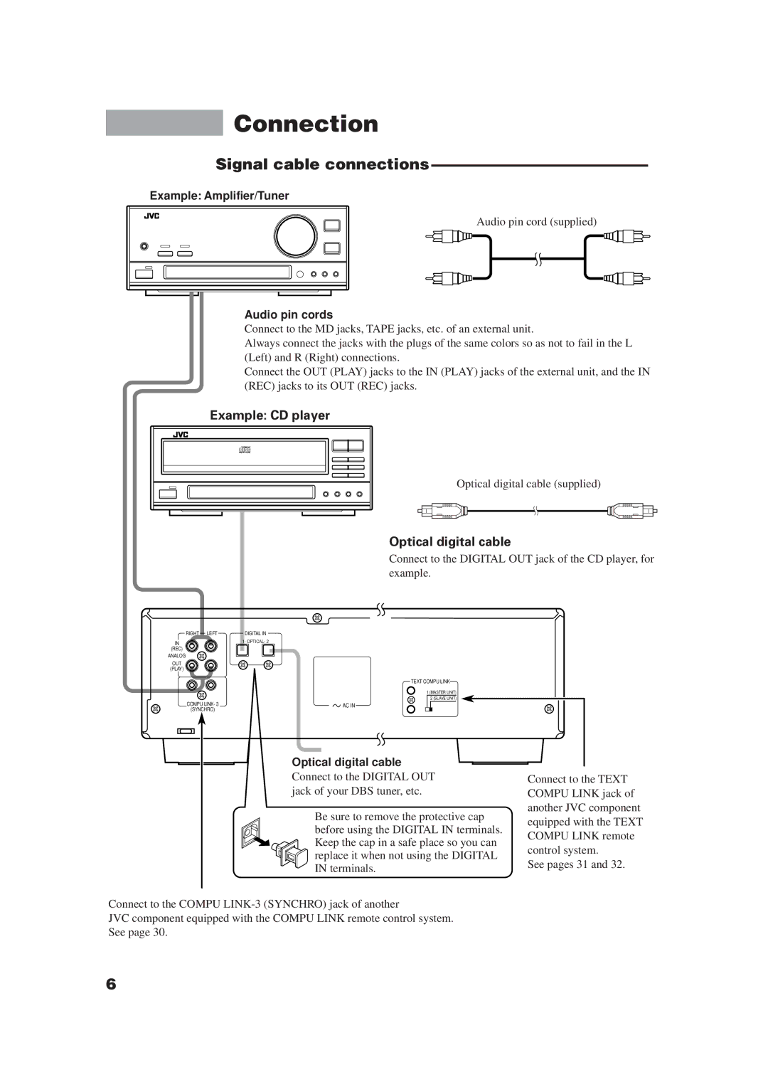
Example: Amplifier/Tuner
Audio pin cord (supplied)
Audio pin cords
Connect to the MD jacks, TAPE jacks, etc. of an external unit.
Always connect the jacks with the plugs of the same colors so as not to fail in the L (Left) and R (Right) connections.
Connect the OUT (PLAY) jacks to the IN (PLAY) jacks of the external unit, and the IN (REC) jacks to its OUT (REC) jacks.
Example: CD player
Optical digital cable (supplied)
Optical digital cable
Connect to the DIGITAL OUT jack of the CD player, for example.
RIGHT LEFT | DIGITAL IN |
IN | 1- OPTICAL- 2 |
(REC) |
|
ANALOG |
|
OUT |
|
(PLAY) |
|
| TEXT COMPU LINK |
| 1 (MASTER UNIT) |
| 2 (SLAVE UNIT) |
COMPU LINK- 3 | AC IN |
(SYNCHRO) |
|
Optical digital cable
Connect to the DIGITAL OUT jack of your DBS tuner, etc.
Be sure to remove the protective cap before using the DIGITAL IN terminals. Keep the cap in a safe place so you can replace it when not using the DIGITAL IN terminals.
Connect to the COMPU
JVC component equipped with the COMPU LINK remote control system. See page 30.
Connect to the TEXT COMPU LINK jack of another JVC component equipped with the TEXT COMPU LINK remote control system.
See pages 31 and 32.
6