Chapter 3: Front Panel
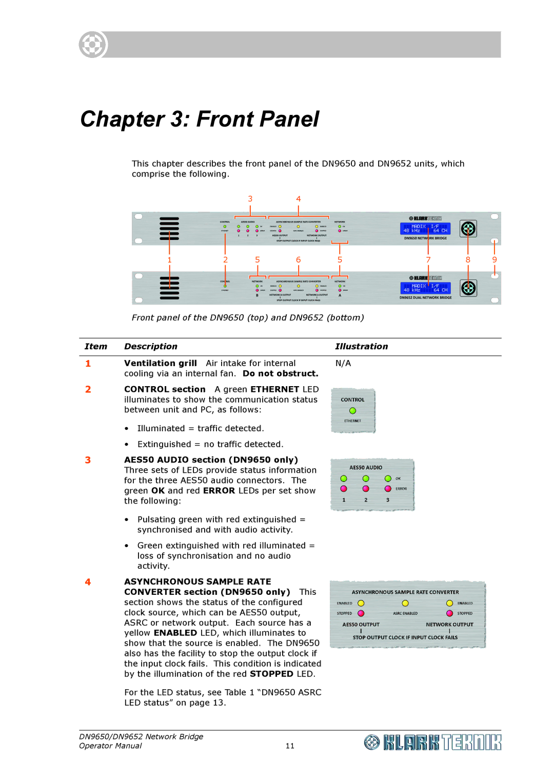
This chapter describes the front panel of the DN9650 and DN9652 units, which comprise the following.
3 4
1 | 2 | 5 |
| 6 | 5 | 7 | 8 | 9 | ||||||||||||
|
|
|
|
|
|
|
|
|
|
|
|
|
|
|
|
|
|
|
|
|
|
|
|
|
|
|
|
|
|
|
|
|
|
|
|
|
|
|
|
|
|
|
|
|
|
|
|
|
|
|
|
|
|
|
|
|
|
|
|
|
|
|
Front panel of the DN9650 (top) and DN9652 (bottom)
Item | Description | Illustration |
|
|
|
1 | Ventilation grill Air intake for internal | N/A |
| cooling via an internal fan. Do not obstruct. |
|
2CONTROL section A green ETHERNET LED illuminates to show the communication status between unit and PC, as follows:
•Illuminated = traffic detected.
•Extinguished = no traffic detected.
3AES50 AUDIO section (DN9650 only) Three sets of LEDs provide status information for the three AES50 audio connectors. The green OK and red ERROR LEDs per set show the following:
•Pulsating green with red extinguished = synchronised and with audio activity.
•Green extinguished with red illuminated = loss of synchronisation and no audio activity.
4ASYNCHRONOUS SAMPLE RATE CONVERTER section (DN9650 only) This section shows the status of the configured clock source, which can be AES50 output, ASRC or network output. Each source has a yellow ENABLED LED, which illuminates to show that the source is enabled. The DN9650 also has the facility to stop the output clock if the input clock fails. This condition is indicated by the illumination of the red STOPPED LED.
For the LED status, see Table 1 “DN9650 ASRC LED status” on page 13.
DN9650/DN9652 Network Bridge |
|
Operator Manual | 11 |