14/20RESAL, 14/20RESA specifications
The Kohler 14/20RESA and 14/20RESAL are prominent generators recognized for their robust design, commitment to efficiency, and reliability in providing backup power for residential and light commercial applications. Kohler, a brand synonymous with quality, delivers these generators with advanced technologies and essential features that cater to the power needs of modern households and small businesses.One of the major features of the Kohler 14/20RESA and 14/20RESAL models is their powerful engine, designed to deliver consistent and reliable performance. These generators are equipped with a high-performance, air-cooled, V-Twin engine that ensures smooth operation and longevity. The ability to run on either natural gas or propane provides versatility, making them suitable for various fuel preferences and availability.
Kohler’s innovative technology is reflected in the generator's Quiet Operation system, which minimizes noise levels, allowing homeowners to enjoy uninterrupted comfort during power outages. The noise-dampening qualities make the units ideal for residential settings, ensuring that they can operate without disturbing the peace of the neighborhood.
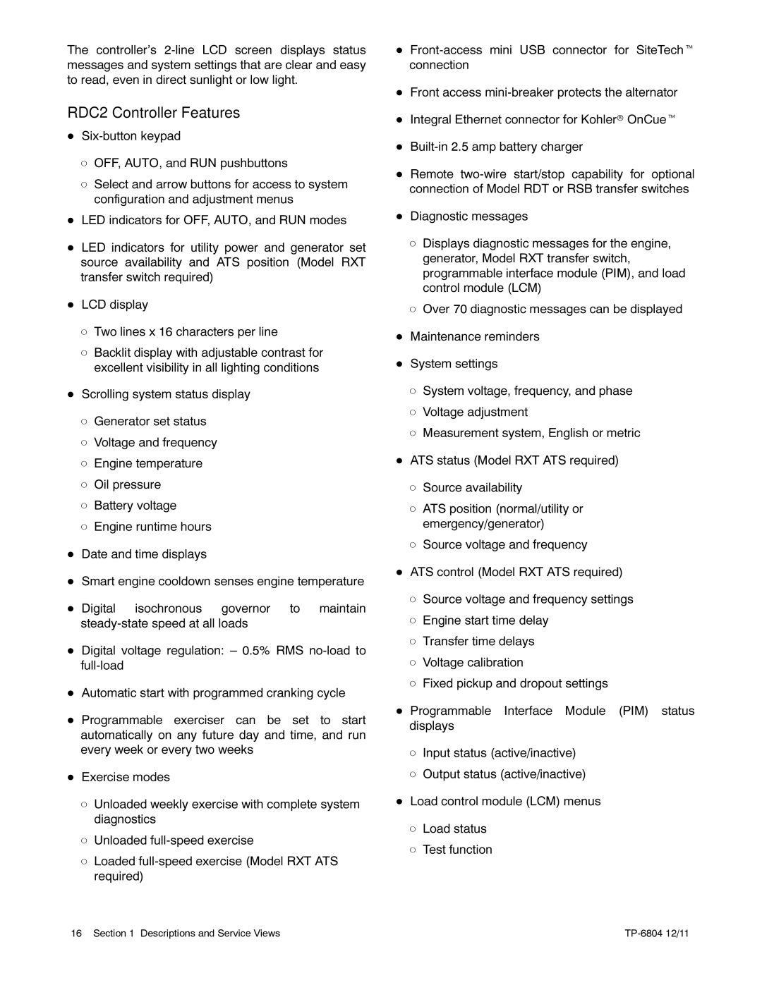
Another standout characteristic of the Kohler 14/20RESA and 14/20RESAL is the advanced digital control system. This system includes an intuitive LCD display that provides real-time data and diagnostics, allowing users to easily monitor the generator's performance. Features such as automatic voltage regulation and overload protection safeguard the generator and connected devices, preventing damage and ensuring stable power output.
The design of these generators emphasizes durability and ease of installation. The robust enclosure protects against environmental elements, making them suitable for outdoor placement. Additionally, the generators feature a compact footprint, which is advantageous in areas with confined spaces.
Residents will also appreciate the auto-start functionality, allowing the generator to turn on automatically during a power outage, ensuring that critical appliances continue to function without interruption. The remote monitoring capabilities also enhance user convenience, enabling owners to check on their generator's status from their smartphones or computers.
Maintenance is simplified with Kohler’s user-friendly design, which includes easy-access service points and a maintenance-free battery. This attention to serviceability enhances the overall user experience, ensuring that the generators operate efficiently for years.
In summary, the Kohler 14/20RESA and 14/20RESAL generators combine powerful performance with advanced technology, solid design, and user-friendly features. Their reliability makes them an excellent choice for anyone needing dependable backup power, whether for home, business, or specialized applications. With Kohler's reputation for quality backing these models, users can rest assured in their purchase decision.