4 Your FC-5 Protocol Translator
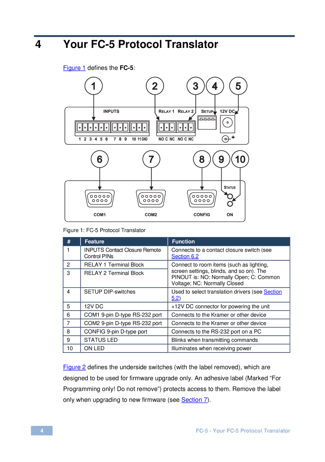
Figure 1 defines the FC-5:
Figure 1: FC-5 Protocol Translator
# |
| Feature |
|
| Function | |
1 |
| INPUTS Contact Closure Remote |
|
| Connects to a contact closure switch (see | |
|
| Control PINs |
|
| Section 6.2 | |
|
|
|
|
|
|
|
2 |
| RELAY 1 Terminal Block |
|
| Connect to room items (such as lighting, | |
3 |
| RELAY 2 Terminal Block |
|
| screen settings, blinds, and so on). The | |
|
|
| PINOUT is: NO: Normally Open; C: Common | |||
|
|
|
|
| ||
|
|
|
|
| Voltage; NC: Normally Closed | |
4 |
| SETUP |
| Used to select translation drivers (see Section | ||
|
|
|
| 5.2) |
| |
5 |
| 12V DC |
|
| +12V DC connector for powering the unit | |
6 |
| COM1 |
|
| Connects to the Kramer or other device | |
7 |
| COM2 |
|
| Connects to the Kramer or other device | |
8 |
| CONFIG |
| Connects to the | ||
9 |
| STATUS LED |
|
| Blinks when transmitting commands | |
10 |
| ON LED |
|
| Illuminates when receiving power | |
Figure 2 defines the underside switches (with the label removed), which are designed to be used for firmware upgrade only. An adhesive label (Marked “For Programming only! Do not remove”) protects access to them. Remove the label only when upgrading to new firmware (see Section 7).
4 |