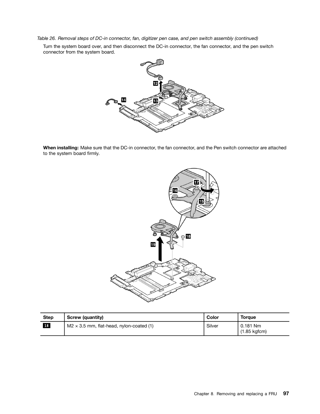
Table 26. Removal steps of
Turn the system board over, and then disconnect the
When installing: Make sure that the
| Step | Screw (quantity) | Color | Torque | |
|
|
|
|
|
|
|
|
| M2 × 3.5 mm, | Silver | 0.181 Nm |
| 18 |
| |||
|
|
|
|
| (1.85 kgfcm) |
|
|
|
|
|
|
Chapter 8. Removing and replacing a FRU 97