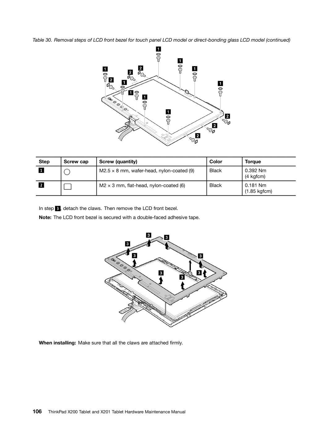
Table 30. Removal steps of LCD front bezel for touch panel LCD model or
| Step |
|
|
| Screw cap | Screw (quantity) | Color | Torque | |
|
|
|
|
|
|
|
|
|
|
|
|
|
|
|
|
| M2.5 × 8 mm, | Black | 0.392 Nm |
| 1 |
|
|
|
|
| |||
|
|
|
|
|
|
|
|
| (4 kgfcm) |
|
|
|
|
|
|
|
|
|
|
|
|
|
|
|
|
| M2 × 3 mm, | Black | 0.181 Nm |
| 2 |
|
|
|
|
| |||
|
|
|
|
|
|
|
|
| (1.85 kgfcm) |
|
|
|
|
|
|
|
|
| |
| In step |
|
| , detach the claws. Then remove the LCD front bezel. |
|
| |||
|
| 3 |
|
| |||||
| Note: The LCD front bezel is secured with a |
|
| ||||||
When installing: Make sure that all the claws are attached firmly.
106ThinkPad X200 Tablet and X201 Tablet Hardware Maintenance Manual