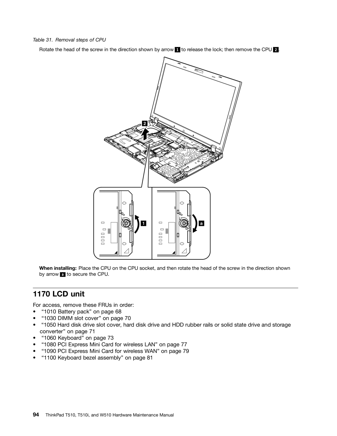
Table 31. Removal steps of CPU
Rotate the head of the screw in the direction shown by arrow
1
to release the lock; then remove the CPU
2.
![]() 2
2![]()
![]()
![]()
![]()
1 | a |
When installing: Place the CPU on the CPU socket, and then rotate the head of the screw in the direction shown by arrow ![]()
![]()
![]() to secure the CPU.
to secure the CPU.
1170 LCD unit
For access, remove these FRUs in order:
•“1010 Battery pack” on page 68
•“1030 DIMM slot cover” on page 70
•“1050 Hard disk drive slot cover, hard disk drive and HDD rubber rails or solid state drive and storage converter” on page 71
•“1060 Keyboard” on page 73
•“1080 PCI Express Mini Card for wireless LAN” on page 77
•“1090 PCI Express Mini Card for wireless WAN” on page 79
•“1100 Keyboard bezel assembly” on page 81