LCD TV
FCC Notice
Class B digital device
Important Safety Instructions
Not to install the TV by the hanging power
Cleaning
Moving
Outdoor antenna grounding
NEC National Electrical Code
Only Hg lamp used LCD TV
Dot Defect
Generated Sound
For LED LCD TV/ LCD TV
Contents
Clock Setting
Set Password & Lock System
100
102
Feature of this TV
Some of these features are not available on all models
Accessories
Front Panel Information
Back Panel Information
32/37/42LD320H, 32/37LD325H
32/37LD310H
Power Cord Socket
AV Audio/Video
Cushioned surface to protect the screen
Stand Instructions
M4 x
Protection Cover
Vesa Wall Mounting
200
Cable Management
Swivel Stand
Desktop Pedestal Installation
Kensington Security System
Screw Provided as parts of the product Desk
Attaching the TV to a Desk
Screws Not provided as parts
LD310H, LD330H Series
Preparation
Antenna or Cable Connection
Antenna Analog or Digital
HD Receiver Setup
Component Connection
Hdmi Connection
DVI to Hdmi Connection
Connect the DVI output of the digital set-top
Box to the HDMI/DVI in 1 jack on the TV
Connect the digital set-top box audio output to
Component Input ports
DVD Setup
Component in Audio jacks on the TV
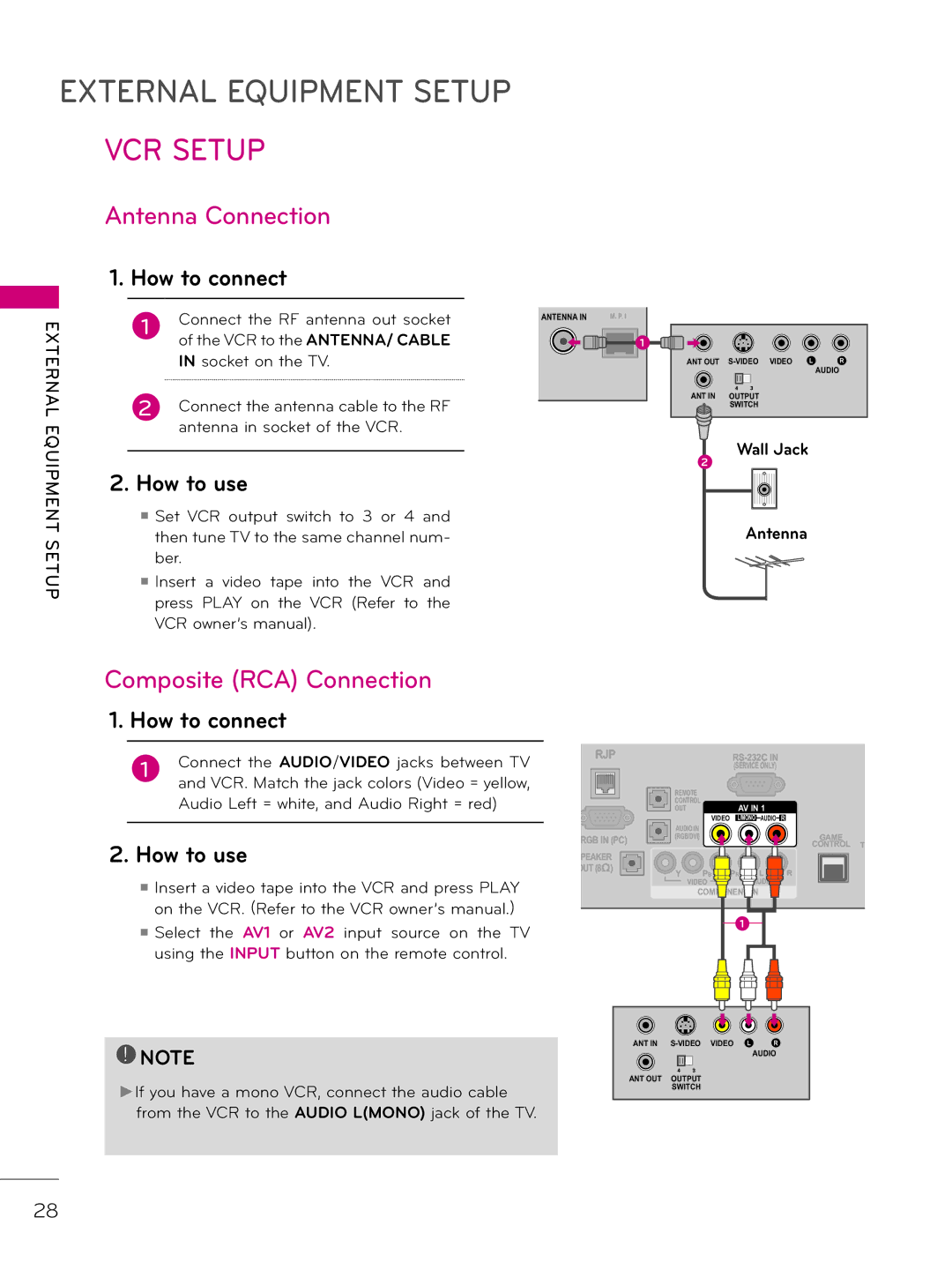
Composite RCA Connection
RJP
VCR Setup
Antenna Connection
TV using the Input button on
Remote control
Camcorder
Select the AV1 or AV2 input source on
After connecting the USB in jack, you
USB Connection
Connect the USB device to the USB
Jack on the side of TV
PC Setup
VGA D-Sub 15 Pin Connection
Input button on the remote control
Connect the DVI output of the PC to
Connect the PC audio output to the Audio
HDMI/DVI in 1 jack on the TV
Supported Display Specifications RGB-PC, HDMI-PC
Screen Setup for PC mode
Select Resolution
Select the desired resolution
Select Picture
Select Auto Config
Start Auto Configuration
Select Yes
Select Screen RGB-PC
Adjustment for screen Position, Size, and Phase
Select Position, Size, or Phase
Start Reset
Select Reset
Select Picture
Remote Control Functions
Watching TV / Channel Control
Volume Adjusts the volume
Color Access special functions in some menus
VCR/DVD Control video cassette recorders or DVD players
Eject Eject the USB device Ratio Change the aspect ratio
Volume Adjustment
First, connect power cord correctly
At this moment, the TV switches to standby mode
Turning on the TV
ON-SCREEN Menus Selection
Select a menu item
Accept the current selection
Return to TV viewing
For LD310H, LD320H, LD325H series
For LD330H, LD333H, LD340H, LD343H, LD345H series
Customer Support
Picture Test / Sound Test
RED Select Customer Support
Return to the previous menu Return to TV viewing
Product/Service Info
Select Customer Support
Return to TV viewing
Return to the previous menu
Channel Setup
Auto Scan Auto Tuning
Select Auto Tuning
Run Auto tuning
Add/Delete Channel Manual Tuning
Select Manual Tuning
Switch to the chosen channel number
Move the pages when the channel list is
Channel Editing
Menu Select Channel
Input List
Select the desired input source
Example Electronic Program Guide
Channel Label
Select Channel Label
Demo Mode
Connection Method
USB Connection
Precautions when using the USB device
Entry Mode
Or Extra Contents
Select MY Media This TV can view JPG image files or play
MP3 audio files
Photo List
Screen Components
On-Screen Display on your model may be slightly different
Supported photo file *.JPG
Mark Mode
Photo Selection
More operations are available in full screen mode
Select the target folder or drive
Select the desired photos
Selected photo is displayed in full size
BGM, Rotate Zoom In, Option, or Hide
Select the Slideshow
Option Set values for Slide Speed and Music Album
Using the Photo List Function
Select Set Photo View , Set Video , or
Enter Set Audio
Select Slide Speed or BGM
Select Picture Mode
Select Sound Mode, Auto Volume, Clear Voice II, or Balance
Move to Photo List
Music List
Select Music List
Music Selection
Music file
Music files are played
Use the CH ꕌꕍ button to navigate in the music
Show the Option menu
Using the Music List Function
Select Set Audio Play or Set Audio
Select Repeat or Random
Voice II , or Balance
Extra Contents
Select Aspect Ratio
Picture Size Aspect Ratio Control
Select the desired picture format
169
Just Scan
Set By Program
Zoom
Select Picture Mode Select Vivid, Standard, Cinema, Sport
Preset Picture Settings Picture Mode
Or Game Return to the previous menu Return to TV viewing
Manual Picture Adjustment User Mode
Picture Improvement Technology Advanced Control
Select Advanced Control
Advanced Control
Signal is inputted through Hdmi
This is produces richer colors
Picture Reset
Initialize the adjusted value
Select Picture Reset
Menu Select Picture
Select Auto Volume
Auto Volume
Select Audio
Adjustment for Clear Voice Level with selecting On
Select Level Make appropriate adjustments
Clear Voice
Menu Select Audio
Sound & Language Control
Balance
Preset Sound Settings Sound Mode
Sound Setting Adjustment User Mode
Adjust the sound to suit your taste and room situations
Audio Reset
TV Speakers ON/OFF Setup
Select Reset Return to TV viewing
Select TV Speaker
This feature operates only in DTV/Cable DTV mode
Audio Language
Select Option Select Language
Select Audio Language
Menus can be shown on the screen in the selected language
ON-SCREEN Menus Language Selection
Select Menu Language
Caption Mode
Analog Broadcasting System Captions
Select CC1-4 or Text1-4
Caption
Select CC1-4,Text1-4, or Service1
Digital Broadcasting System Captions
Caption Option
Select Digital Option
Clock Setting
Auto Clock Setup
Time Setting
Manual Clock Setup
Auto ON/OFF Time Setting
Select Repeat
Mon.~Sat. , Sat.~ Sun. , or Sun
Select and set Hour or Minute
Sleep Timer Setting
Auto SHUT-OFF Setting
Select Sleep Timer
Select Auto Off
SET Password & Lock System
Setting up Your Password
Set Password
Change the password by inputting a new password twice
Enter Select Lock Input the password
Select Set Password Choose any 4 digits for your new
Lock System
Select Lock System
Channel Blocking
Select Block Channel
Movie Rating Mpaa
Movie & TV Rating
Select Movie Rating
Select TV Rating-Children Select Age or Fantasy Violence
TV Rating Children
Select Lock
TV Rating General
Downloadable Rating
Select Downloadable Rating
External Input Blocking
Enables you to block an input
Select Input Block
Troubleshooting
Install new batteries
Try another channel. The problem may be with the broadcast
Directly at the TV
No output from one Adjust Balance in menu option
Use normal MP3 file
Maintenance
Product Specifications
101
IR Code
Code Function
Open Source License
Version 2, June
104
105
106
GNU Lesser General Public License
108
109
110
111
Mozilla Public License
113
114
115
116
Model Serial
206-4163 Rev B
Copyright 2011, LG Electronics U.S.A., Inc
For Customer Support/Service, please call
Important Safety Instructions
Outdoor Antenna Grounding
Table of Contents
Setup Checklist
Setup Checklist / Overview
Commercial Mode Setup Overview
ProCentric TV Interactive Menu Features
Channel Guide
Information
Remote Help
LD320H/LD325H Rear Jack Panel
AUDIO/VIDEO
Side Connections Panel / RF Antenna & MPI Connections
Side Connections Panel
RF Antenna & MPI Connections
2 Input
Installer Remote
Installer Overview
Cloning
Installer Remote Control Typical Key Functions
Flashbk Flashback
Set Installer Menu items
Commercial Mode Setup for Master TV
Set up TV features
Verify the TV setup
Run Auto Tuning Channel Search
Lock the channel lineup
Installer Menu
Accessing the Installer Menu
Using the Installer Menu
Exiting the Installer Menu and Activating Updates
Installer Menu Items 000 through
Brief Description of Function and Comments
Installer Menu Items 073 through
CH not Avble
Detailed Descriptions of Installer Menu Items
Installer Sequence
Sleep Timer
AUX Status
Procentric
TV Setup Menus Overview
Editing/Adding Channel Icons and/or Labels
To perform channel editing/labeling
FTG Mode of Operation
FTG Configuration Overview
Configuration Application manual for further information
Delete
FTG Installer Menu Configuration Utility Overview
Installer Defaults
Clonable Menu Features
Cloning Overview / Clonable Menu Features
Before you begin cloning
Cloning Procedures
Learn Setup from Master TV
Teach Master TV Setup to Target TV
USB Cloning Notes
TLL-1100A Cloning Notes
Or Catv
Optional Set the Clock
LT2002 Cloning Notes
LT2002 Clone Programmer
From previous
Remote Jack Pack Setup
Remote Jack Pack / TV Connections & Setup
TV Connections
Checking the Software Versions
Upgrading TV/PTC Software
Splash Screen Image File Guidelines
Downloading a Splash Screen Image
Reference Power Consumption Settings
Static
Reference TV Camport Auto Sense Operation
Camport Side Video Functionality Control
Camport Operation Stand-alone
Camport Operation FTG or PPV
Reference TV Aux Input Configuration
Enable
TV Standby State TV Power On State
Reference b-LAN Setup & Overview
LAN Power 001 Default Off 007
RJP Model List Legacy Models Scaler Models
Reference RJP Model List and Input Auto-sensing Hierarchy
RJP Input Auto-sensing Hierarchy Priority Video Audio
Troubleshooting
General Troubleshooting
Troubleshooting Flow Chart
Controller Quick Check
FTG Operation Troubleshooting
Commercial Mode Check / FTG Operation Troubleshooting
Symptom Possible Causes Solutions
Clone Programmer Troubleshooting
Reset Clone Programmer After Static Shock
Symptom Possible Causes Possible Solutions Clone Programmer
Master and Target TVs
Glossary of Terms
OHM RF Cable
Document Revision History
Document Revision History / Notes
Date Description
For Customer Support/Service, please call
206-4177 Rev a
Copyright 2011, LG Electronics U.S.A., Inc
Power Cord Polarization
206-4177
For products where thermal deformation is required
Adding Channel Icons / Custom Channel Labels
Setup Checklist / Commercial Mode Setup Overview
ProCentric TV Interactive Menu Features
LD310H Rear Jack Panel
RGB in PC Connection for RGB output from PC
USB
206-4177
Returns one level to the previous menu/ display
Fact Default
Channel
Navigation within the Installer Menu
Changing Installer Menu Settings
Installer Menu Items 000 through
091 YPrPb2 EN Set to 1 to enable Hdmi 2 input 094
Detailed Descriptions of Installer Menu Items
Sleep Timer
= Black = Cyan
Back Lighting
TV Setup Menus Overview
Enter the TV Installer Menu Press Menu repeatedly
Cloning Overview / Clonable Menu Features
Updating
TLL-1100A Cloning Notes
Optional Set the Clock
Cable, poor contacts, or other
From previous
FTG Mode Overview / Determining the TV Operating Mode
Determining the TV Operating Mode
FTG Mode of Operation
Learning an FMA Configuration File from a TV
Optional Manual Configuration / Setup for a TV
FTG Channel Map Configuration Utility Overview
FTG Channel Map Editor Overview
FTG Installer Menu Configuration Utility Overview
FMA Configuration Utility Overview
V1.00.001
Splash Screen Image File Guidelines
32LD310H 37LD310H Power
Reference TV Camport Auto Sense Operation
Reference TV Aux Input Configuration
Troubleshooting
End Bad PPV Card
Leave the TV set on Bad Go to Installer Menu
Clone Programmer Troubleshooting
Glossary of Terms
Date Description January Revision a New Document
For Customer Support/Service, please call
206-4186 Rev a
206-4186
Important Safety Instructions
Outdoor Antenna Grounding
Table of Contents
Setup Checklist
Setup Checklist / Overview
Commercial Mode Setup Overview
Help
LD340H/LD343H/LD345H Rear Jack Panel
AUDIO/VIDEO
Side Connections Panel / RF Antenna Connection
Side Connections Panel
RF Antenna Connection
2 Input
XxLD340H PTC Installer Menu 000
Back
Commercial Mode Setup for Master TV
Set Installer Menu items
Set up TV features
Run Auto Tuning Channel Search
Verify the TV setup
Lock the channel lineup
Installer Menu
Accessing the Installer Menu
Using the Installer Menu
Exiting the Installer Menu and Activating Updates
Installer Menu Items 000 through
Brief Description of Function and Comments
Installer Menu Items 073 through
CH not Avble
Detailed Descriptions of Installer Menu Items
Installer Sequence
Sleep Timer
AUX Status
Procentric
TV Setup Menus Overview
Editing/Adding Channel Icons and/or Labels
To perform channel editing/labeling
Clonable Menu Features
Cloning Overview / Clonable Menu Features
Before you begin cloning
Cloning Procedures
Learn Setup from Master TV
Teach Master TV Setup to Target TV
USB Cloning Notes
TLL-1100A Cloning Notes
Or Catv
Optional Set the Clock
7-6 + Enter
LT2002 Cloning Notes
LT2002 Clone Programmer
From previous
FTG Mode of Operation Overview
FTG Mode via CPU or EBL
Determining the TV Operating Mode
Aspect Ratio
FTG Mode via CPU
Teaching FMA Configuration to a TV
Learning an FMA Configuration File from a TV
Optional Manual Configuration / Setup for a TV
FTG Mode via EBL
FTG Configuration Application Utilities Overview
FTG Channel Map Configuration Utility
Update
FTG Channel Map Editor
FTG Installer Menu Configuration Utility
Installer Defaults
FMA Configuration Utility
Remote Jack Pack Setup
Remote Jack Pack / TV Connections & Setup
TV Connections
Checking the Software Versions
Upgrading TV/PTC Software
Splash Screen Image File Guidelines
Downloading a Splash Screen Image
Reference Power Consumption Settings
Static
Reference TV Camport Auto Sense Operation
Camport Side Video Functionality Control
Camport Operation Stand-alone
Camport Operation FTG or PPV
Reference TV Aux Input Configuration
Enable
TV Standby State TV Power On State
Reference b-LAN Setup & Overview
LAN Power 001 Default Off
RJP Model List Legacy Models Scaler Models
Reference RJP Model List and Input Auto-sensing Hierarchy
RJP Input Auto-sensing Hierarchy Priority Video Audio
FTG Mode via CPU
Resetting a TV to Pass-through Mode
FTG Mode via EBL
Troubleshooting
General Troubleshooting
Troubleshooting Flow Chart
Controller Quick Check
FTG Operation Troubleshooting
Commercial Mode Check / FTG Operation Troubleshooting
Symptom Possible Causes Solutions
Symptom Possible Causes Possible Solutions Clone Programmer
Clone Programmer Troubleshooting
Master and Target TVs
Glossary of Terms
OHM RF Cable
Document Revision History
Document Revision History / Notes
Date Description May Revision a New document
For Customer Support/Service, please call
206-4185 Rev a
206-4185
206-4185
Outdoor Antenna Grounding
Commercial Mode Setup for Master TV . . . .12 - 13
Cloning Overview / Clonable Menu Features
Setup Checklist / Commercial Mode Setup Overview
Portal
LD330H/LD333H Rear Jack Panel
Component
Antenna
XxLD330H PTC Installer Menu 000
Info
Commercial Mode Setup for Master TV
Channel
Installer Menu
Installer Menu Items 000 through
Set to 0 to disable RGB input. Set to 1 to enable RGB input
Detailed Descriptions of Installer Menu Items
Sleep Timer
EN. CH-T COL. Enable Channel-Time Custom Color
Procentric
Channel Picture Audio
XYZ
Manual Tuning TV Speaker Channel Edit
XxLD330H-UA00001.TLL
TLL-1100A Cloning Notes
Optional Set the Clock
Read the Important Cloning
From previous
FTG Mode of Operation
FTG Mode Overview
FTG Mode of Operation
Teaching FMA Configuration to a TV
Learning an FMA Configuration File from a TV
Optional Manual Configuration / Setup for a TV
FTG Configuration Application Utilities Overview
FTG Channel Map Editor
FTG Installer Menu Configuration Utility
FMA Configuration List
PTC Version
Splash Screen Image File Guidelines
32LD330H 37LD330H 32LD333H 37LD333H
Reference TV Camport Auto Sense Operation
Reference TV Aux Input Configuration
Reference Resetting a TV to Pass-through Mode
Symptom Possible Causes Possible Solutions Installation
End Bad PPV Card
Leave the TV set on Bad Go to Installer Menu
Symptom Possible Causes Possible Solutions
Glossary of Terms
Document Revision History / Notes
For Customer Support/Service, please call