| 101 |
| 80 |
3/8 X 1-1/4” 88 | 5 |
|
| 1/2” |
| LOW |
| 86 HEIGHT |
54 | 84 |
|
1/2 X 1-1/4” 93 | |
37 | |
116 | 85 |
| 100 |
4 | |
38 | |
14 | |
76 | |
80 | |
3/8 X 1-1/4” 88 | |
97 1/2 X 6-1/2” | |
FIGURE 8 | |
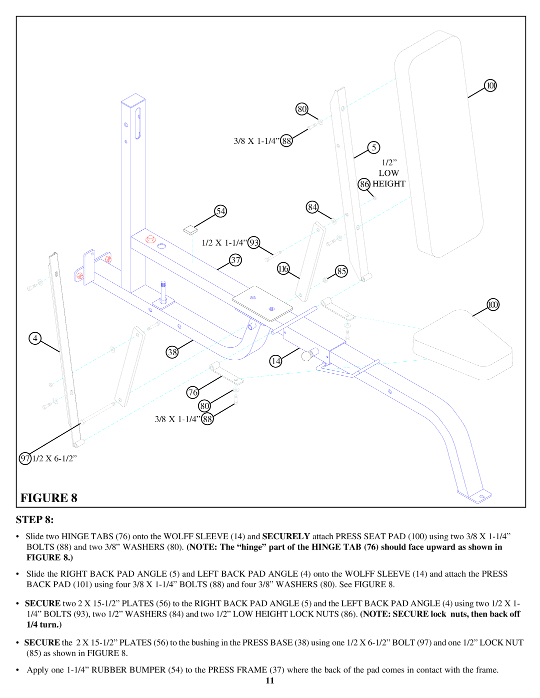
STEP 8:
•Slide two HINGE TABS (76) onto the WOLFF SLEEVE (14) and SECURELY attach PRESS SEAT PAD (100) using two 3/8 X 1-1/4” BOLTS (88) and two 3/8” WASHERS (80). (NOTE: The “hinge” part of the HINGE TAB (76) should face upward as shown in
FIGURE 8.)
•Slide the RIGHT BACK PAD ANGLE (5) and LEFT BACK PAD ANGLE (4) onto the WOLFF SLEEVE (14) and attach the PRESS BACK PAD (101) using four 3/8 X 1-1/4” BOLTS (88) and four 3/8” WASHERS (80). See FIGURE 8.
•SECURE two 2 X 15-1/2” PLATES (56) to the RIGHT BACK PAD ANGLE (5) and the LEFT BACK PAD ANGLE (4) using two 1/2 X 1- 1/4” BOLTS (93), two 1/2” WASHERS (84) and two 1/2” LOW HEIGHT LOCK NUTS (86). (NOTE: SECURE lock nuts, then back off 1/4 turn.)
•SECURE the 2 X 15-1/2” PLATES (56) to the bushing in the PRESS BASE (38) using one 1/2 X 6-1/2” BOLT (97) and one 1/2” LOCK NUT (85) as shown in FIGURE 8.
•Apply one 1-1/4” RUBBER BUMPER (54) to the PRESS FRAME (37) where the back of the pad comes in contact with the frame.
11