82 | 48 |
30 | |
69 |
|
| 116 |
LAT CABLE 42 | 90 |
| 3/8 X |
FIGURE 22 |
|
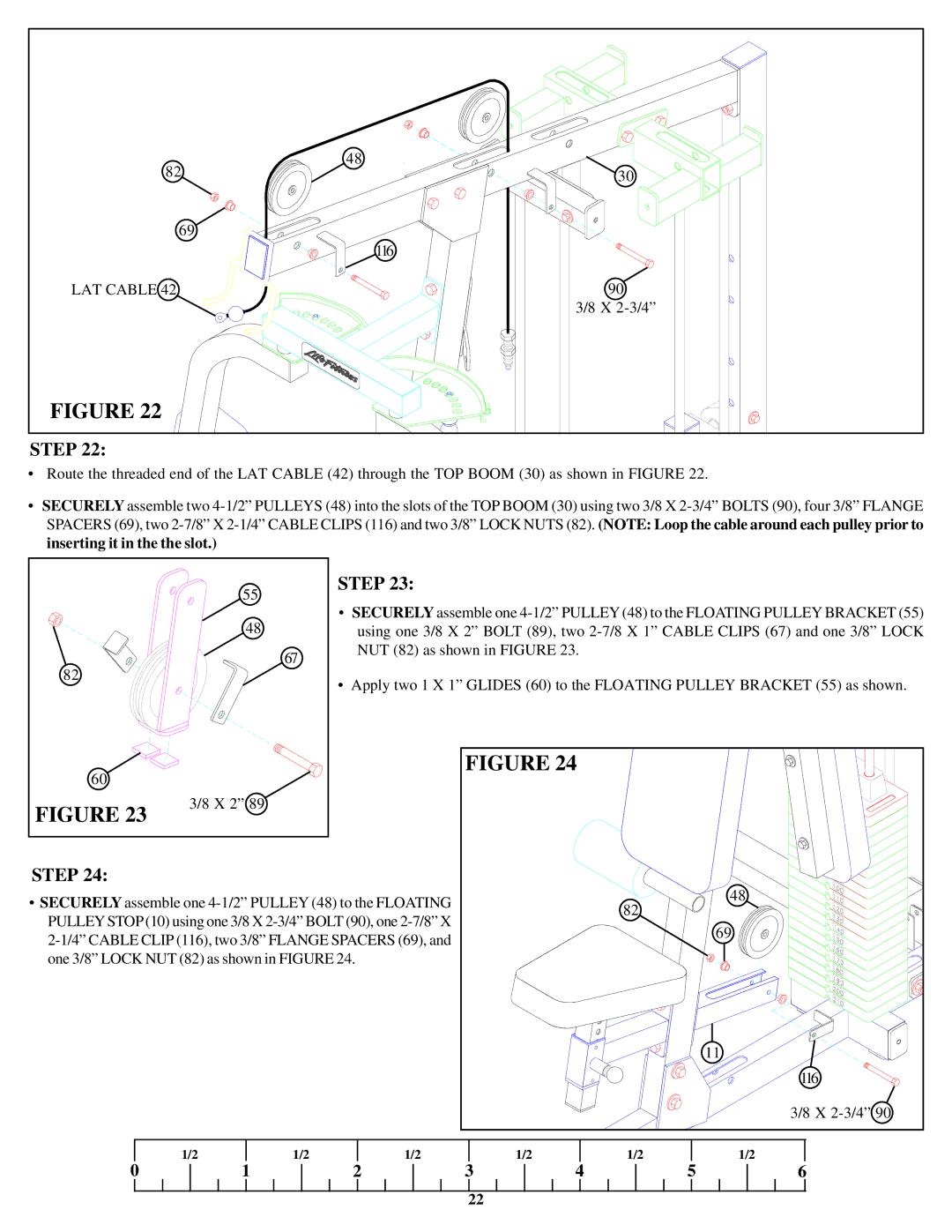
STEP 22:
•Route the threaded end of the LAT CABLE (42) through the TOP BOOM (30) as shown in FIGURE 22.
•SECURELY assemble two
|
| 55 | STEP 23: |
|
|
|
|
|
| • SECURELY assemble one | |||||
|
| 48 | |||||
|
| using one 3/8 X 2” BOLT (89), two | |||||
|
| 67 | NUT (82) as shown in FIGURE 23. |
|
| ||
82 |
|
|
|
|
|
| |
|
| • Apply two 1 X 1” GLIDES (60) to the FLOATING PULLEY BRACKET (55) as shown. | |||||
|
|
| |||||
60 |
|
|
| FIGURE 24 |
|
| |
|
|
|
|
|
|
| |
FIGURE 23 | 3/8 X 2” 89 |
|
|
|
|
| |
|
|
|
|
|
|
| |
STEP 24: |
|
|
|
|
|
| 48 |
• SECURELY assemble one |
| 82 |
| ||||
|
|
| |||||
PULLEY STOP(10) using one 3/8 X |
|
|
| ||||
|
|
| 69 | ||||
|
|
| |||||
|
|
|
| ||||
one 3/8” LOCK NUT (82) as shown in FIGURE 24. |
|
|
|
| |||
|
|
|
|
|
|
| 11 |
|
|
|
|
|
|
| 116 |
|
|
|
|
|
|
| 3/8 X |
0 | 1/2 | 1/2 | 1/2 | 1/2 | 1/2 | 5 | 1/2 |
| 1 | 2 | 3 | 4 | 6 | ||
|
|
|
| 22 |
|
|
|