48
82
46 PEC CABLE
67
3/8 X 2” 89
FIGURE 29 | 26 |
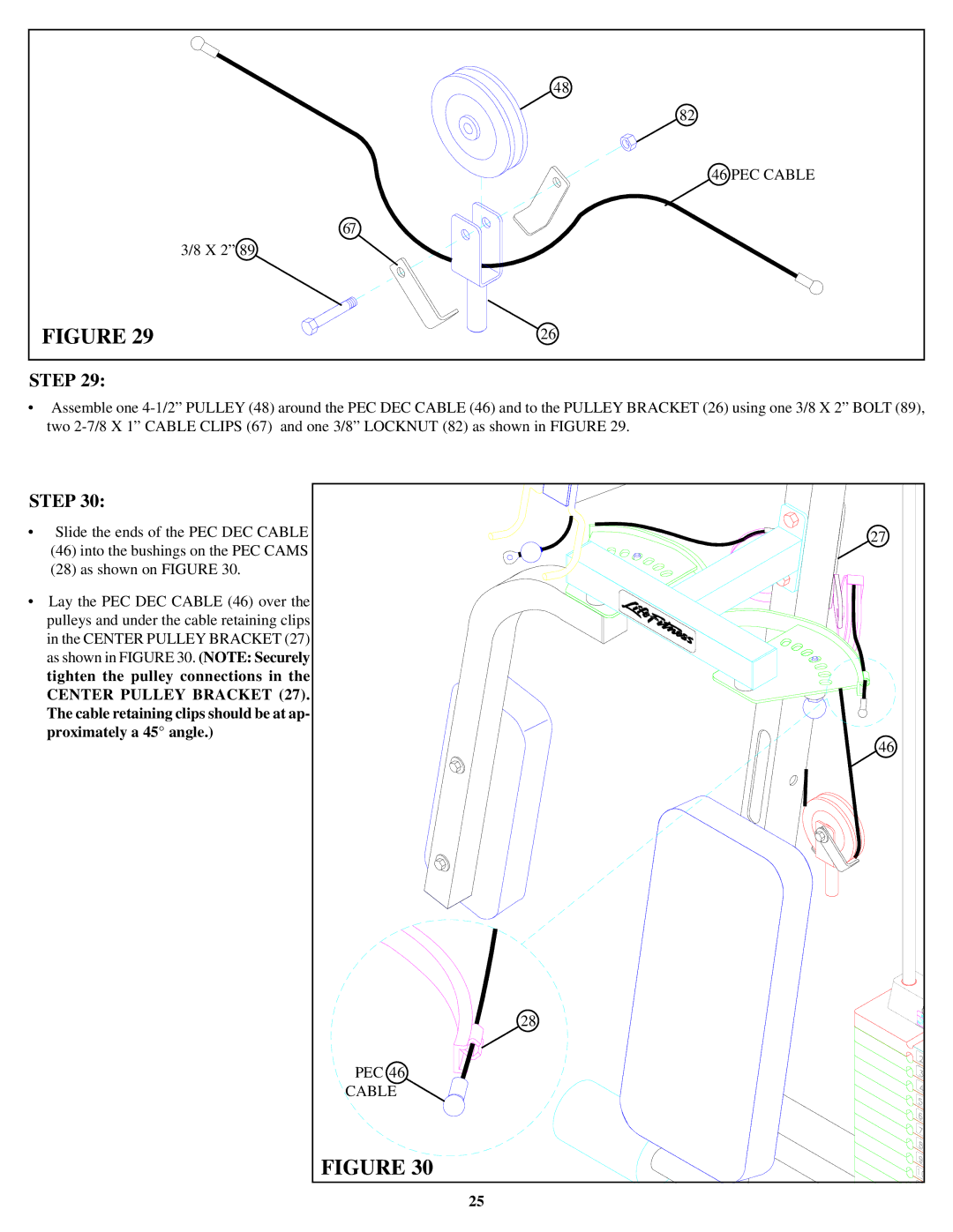
STEP 29:
•Assemble one
STEP 30:
•Slide the ends of the PEC DEC CABLE
(46)into the bushings on the PEC CAMS
(28)as shown on FIGURE 30.
•Lay the PEC DEC CABLE (46) over the pulleys and under the cable retaining clips in the CENTER PULLEY BRACKET (27) as shown in FIGURE 30. (NOTE: Securely tighten the pulley connections in the CENTER PULLEY BRACKET (27). The cable retaining clips should be at ap- proximately a 45° angle.)
27 |
46 |
28 |
PEC 46 |
CABLE |
FIGURE 30 |
25 |