105 |
| |
| 29 | |
| 92 3/8 X 4” | |
| 80 | |
104 |
| |
13 | 1/2” | |
| ||
80 | LOW | |
HEIGHT 86 | ||
| ||
3/8 X | 11 | |
1/2 X 4” 96 |
| |
12 |
| |
| 62 | |
FIGURE 3 |
|
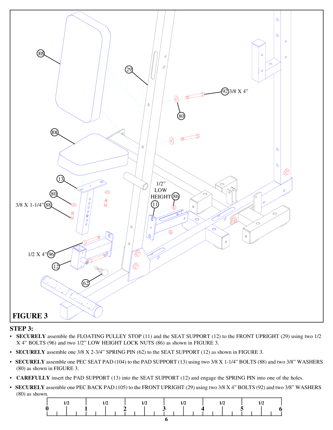
STEP 3:
•SECURELY assemble the FLOATING PULLEY STOP (11) and the SEAT SUPPORT (12) to the FRONT UPRIGHT (29) using two 1/2 X 4” BOLTS (96) and two 1/2” LOW HEIGHT LOCK NUTS (86) as shown in FIGURE 3.
•SECURELY assemble one 3/8 X
•SECURELY assemble one PEC SEAT PAD (104) to the PAD SUPPORT (13) using two 3/8 X
(80)as shown in FIGURE 3.
•CAREFULLY insert the PAD SUPPORT (13) into the SEAT SUPPORT (12) and engage the SPRING PIN into one of the holes.
•SECURELY assemble one PEC BACK PAD (105) to the FRONT UPRIGHT (29) using two 3/8 X 4” BOLTS (92) and two 3/8” WASHERS
(80)as shown.
| 1/2 |
| 1/2 |
| 1/2 |
| 1/2 |
| 1/2 |
|
| 1/2 |
| |||||||||||
0 |
|
| 1 |
|
| 2 |
|
| 3 |
|
| 4 |
|
| 5 |
| 6 | |||||||
|
|
|
|
|
|
|
|
|
|
|
|
|
|
|
|
|
|
|
|
|
|
|
|
|
6
