|
|
| 60 |
|
| 1/2 X 4” 96 |
|
|
|
| 10 |
| 29 | 27 86 |
|
|
| ||
|
|
|
| 1/2” |
|
|
|
| LOW HEIGHT |
|
|
| 79 |
|
|
| 72 | 41 |
|
|
|
|
| |
|
|
| 40 |
|
|
|
| 28 |
|
7 | 71 |
|
|
|
| 71 |
| 6 |
|
| 84 |
|
| |
|
|
|
| |
| 85 |
|
|
|
| 62 |
| 99 |
|
|
|
|
| |
|
| 80 |
|
|
FIGURE 4 | 3/8 X |
|
|
|
|
|
|
|
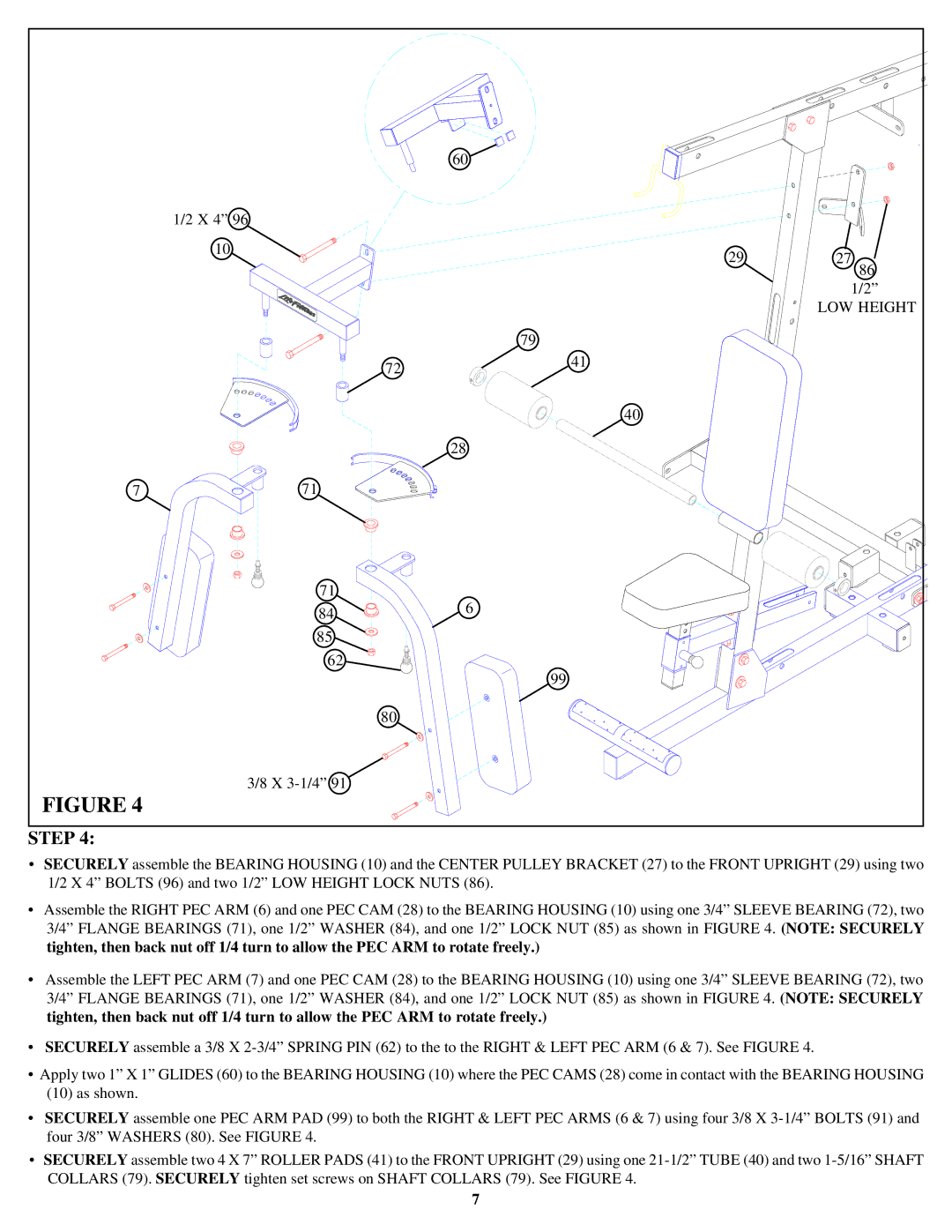
STEP 4:
•SECURELY assemble the BEARING HOUSING (10) and the CENTER PULLEY BRACKET (27) to the FRONT UPRIGHT (29) using two 1/2 X 4” BOLTS (96) and two 1/2” LOW HEIGHT LOCK NUTS (86).
•Assemble the RIGHT PEC ARM (6) and one PEC CAM (28) to the BEARING HOUSING (10) using one 3/4” SLEEVE BEARING (72), two 3/4” FLANGE BEARINGS (71), one 1/2” WASHER (84), and one 1/2” LOCK NUT (85) as shown in FIGURE 4. (NOTE: SECURELY tighten, then back nut off 1/4 turn to allow the PEC ARM to rotate freely.)
•Assemble the LEFT PEC ARM (7) and one PEC CAM (28) to the BEARING HOUSING (10) using one 3/4” SLEEVE BEARING (72), two 3/4” FLANGE BEARINGS (71), one 1/2” WASHER (84), and one 1/2” LOCK NUT (85) as shown in FIGURE 4. (NOTE: SECURELY tighten, then back nut off 1/4 turn to allow the PEC ARM to rotate freely.)
•SECURELY assemble a 3/8 X
•Apply two 1” X 1” GLIDES (60) to the BEARING HOUSING (10) where the PEC CAMS (28) come in contact with the BEARING HOUSING
(10)as shown.
•SECURELY assemble one PEC ARM PAD (99) to both the RIGHT & LEFT PEC ARMS (6 & 7) using four 3/8 X
•SECURELY assemble two 4 X 7” ROLLER PADS (41) to the FRONT UPRIGHT (29) using one
7