| 94 1/2 X 3” |
| 38 |
| 1 |
| 84 |
| 85 |
| 86 1/2” LOW HEIGHT |
94 1/2 X 3” | 35 |
| 84 |
| 85 |
25 |
|
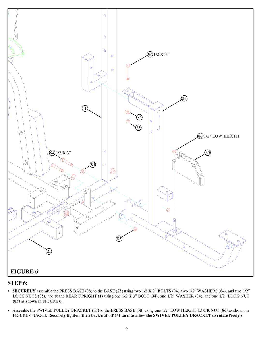
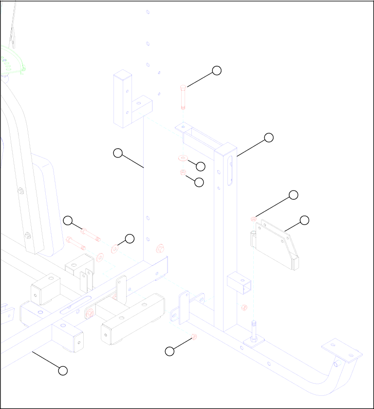
FIGURE 6 |
|
STEP 6:
•SECURELY assemble the PRESS BASE (38) to the BASE (25) using two 1/2 X 3” BOLTS (94), two 1/2” WASHERS (84), and two 1/2” LOCK NUTS (85), and to the REAR UPRIGHT (1) using one 1/2 X 3” BOLT (94), one 1/2” WASHER (84), and one 1/2” LOCK NUT (85) as shown in FIGURE 6.
•Assemble the SWIVEL PULLEY BRACKET (35) to the PRESS BASE (38) using one 1/2” LOW HEIGHT LOCK NUT (86) as shown in FIGURE 6. (NOTE: Securely tighten, then back nut off 1/4 turn to allow the SWIVEL PULLEY BRACKET to rotate freely.)
9