85 |
21 |
20 |
30 |
19 |
95 1/2 X |
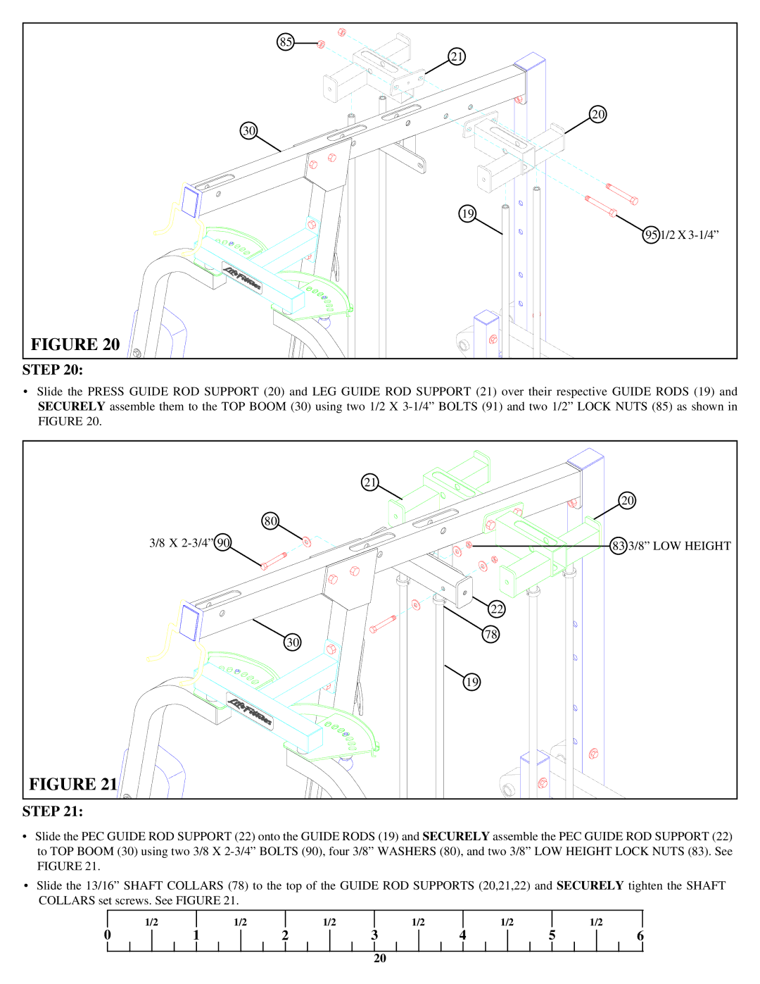
FIGURE 20 |
STEP 20:
•Slide the PRESS GUIDE ROD SUPPORT (20) and LEG GUIDE ROD SUPPORT (21) over their respective GUIDE RODS (19) and SECURELY assemble them to the TOP BOOM (30) using two 1/2 X
|
| 21 |
|
| 20 |
| 80 |
|
3/8 X |
| 83 3/8” LOW HEIGHT |
|
| 22 |
| 30 | 78 |
|
| |
|
| 19 |
FIGURE 21 |
|
|
STEP 21:
•Slide the PEC GUIDE ROD SUPPORT (22) onto the GUIDE RODS (19) and SECURELY assemble the PEC GUIDE ROD SUPPORT (22) to TOP BOOM (30) using two 3/8 X
•Slide the 13/16” SHAFT COLLARS (78) to the top of the GUIDE ROD SUPPORTS (20,21,22) and SECURELY tighten the SHAFT COLLARS set screws. See FIGURE 21.
| 1/2 |
| 1/2 |
| 1/2 |
| 1/2 |
| 1/2 |
|
| 1/2 |
0 | 1 | 2 | 3 | 4 | 5 | 6 | ||||||
20