43 LEG
48 CABLE
23 | 82 |
80 67
3/8 X 2” 89
FIGURE 40
STEP 40:
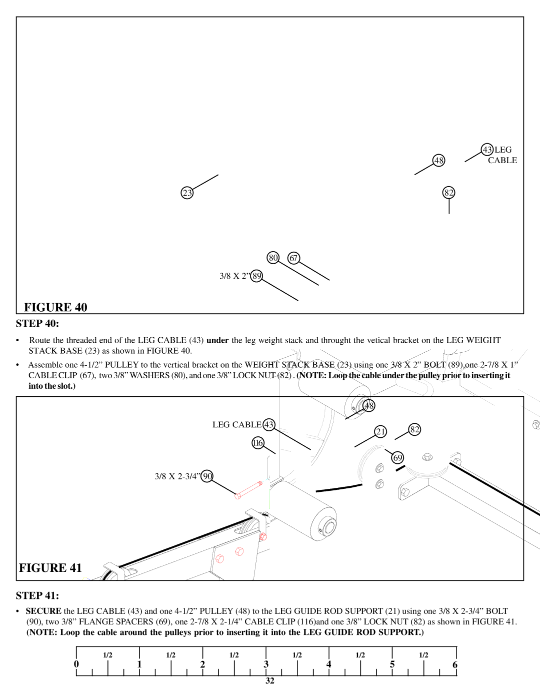
•Route the threaded end of the LEG CABLE (43) under the leg weight stack and throught the vetical bracket on the LEG WEIGHT
STACK BASE (23) as shown in FIGURE 40.
•Assemble one
into the slot.)
| 48 |
| |
LEG CABLE 43 | 21 | 82 | |
116 | |||
|
| ||
|
| 69 |
3/8 X
FIGURE 41
STEP 41:
•SECURE the LEG CABLE (43) and one
(NOTE: Loop the cable around the pulleys prior to inserting it into the LEG GUIDE ROD SUPPORT.)
| 1/2 |
| 1/2 |
| 1/2 |
| 1/2 |
| 1/2 |
|
| 1/2 |
0 | 1 | 2 | 3 | 4 | 5 | 6 | ||||||
32
