|
| 117 |
| 45 AB CABLE | |
| 80 |
|
| SEE DETAIL 31 |
|
|
| 48 |
| 69 | 118 |
| 95 3/8 X |
|
FIGURE 31 | DETAIL 31 |
|
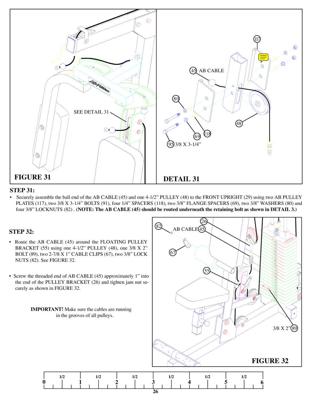
STEP 31:
•Securely assemble the ball end of the AB CABLE (45) and one
|
|
|
| 82 |
| 26 |
|
|
STEP 32: |
|
| AB CABLE 45 |
|
| |||
|
|
|
|
| ||||
|
|
|
|
|
|
| ||
• | Route the AB CABLE (45) around the FLOATING PULLEY |
|
|
|
| |||
| BRACKET (55) using one | 67 |
|
|
| |||
| BOLT (89), two |
|
|
| ||||
| NUTS (82). See FIGURE 32. |
|
|
|
|
|
| |
• | Screw the threaded end of AB CABLE (45) approximately 1” into |
| 55 |
|
| |||
|
|
|
| |||||
| the end of the PULLEY BRACKET (26) and tighten jam nut se- |
|
|
|
| |||
| curely as shown in FIGURE 32. |
|
|
|
|
|
| |
| IMPORTANT! Make sure the cables are running |
|
|
|
|
| ||
|
| in the grooves of all pulleys. |
|
|
|
|
| |
|
|
|
|
|
|
|
| 3/8 X 2” 89 |
|
|
|
|
|
|
|
| FIGURE 32 |
| 0 | 1/2 | 1/2 | 1/2 | 1/2 | 1/2 | 5 | 1/2 |
| 1 | 2 | 3 |
| 4 | 6 | ||
|
|
|
| 26 |
|
|
|
|