42 |
LAT |
CABLE |
50 |
53 |
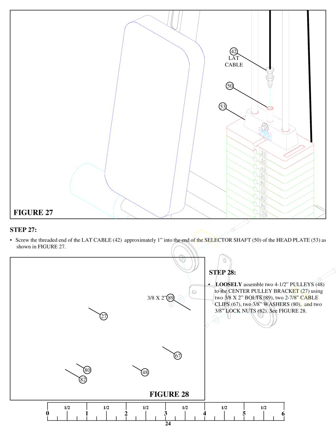
FIGURE 27 |
STEP 27:
•Screw the threaded end of the LAT CABLE (42) approximately 1” into the end of the SELECTOR SHAFT (50) of the HEAD PLATE (53) as shown in FIGURE 27.
3/8 X 2” 89
27
67
8048
82
FIGURE 28
STEP 28:
•LOOSELY assemble two
| 1/2 |
| 1/2 |
| 1/2 |
| 1/2 |
| 1/2 |
|
| 1/2 |
0 | 1 | 2 | 3 | 4 | 5 | 6 | ||||||
24
