300 DLX, 300 D specifications
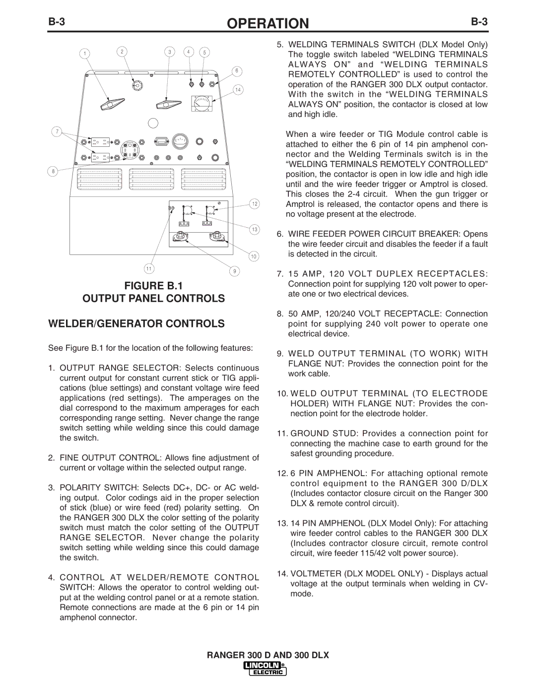
The Lincoln Electric 300 D and 300 DLX are portable diesel engine-driven welding generators that stand out for their versatility, reliability, and advanced features tailored for industrial, commercial, and construction applications. These machines are part of Lincoln Electric's commitment to delivering high-quality welding power solutions that can withstand the rigors of demanding work environments.One of the key features of the Lincoln Electric 300 D and 300 DLX is their powerful engine, capable of generating consistent and reliable welding output. The machines are equipped with a robust, air-cooled, four-cycle diesel engine that ensures long run times and excellent fuel efficiency, making them ideal for extended job sites where access to power sources may be limited.
Both models provide an impressive welding output range, with the ability to weld continuously at high amperage. This high amperage capability allows welders to tackle a wide variety of applications, including stick, TIG, and MIG welding. The 300 DLX model boasts enhanced features such as increased welding output, which caters to heavy-duty applications, while the 300 D remains a solid choice for standard applications.
In terms of technology, the 300 DLX incorporates advanced digital technology that enables optimal arc performance and increased control over welding parameters. This feature not only improves weld quality but also enhances the overall user experience. The intuitive user interface allows welders to easily navigate through settings, making adjustments quick and efficient.
Both models also offer exceptional durability. Their rugged construction is designed to endure harsh job site conditions, and they are built with weather-resistant enclosures to protect vital components from the elements. The large fuel tanks ensure that operators can work for extended periods without frequent refueling, further enhancing productivity.
Additionally, the 300 D and 300 DLX are equipped with a variety of output options, including 115V and 230V auxiliary power, which can be utilized for powering tools and other equipment on-site. This versatility makes these generators not just welders, but comprehensive power solutions for a wide array of tasks.
In summary, the Lincoln Electric 300 D and 300 DLX are exceptional diesel engine-driven welding generators that offer unmatched power, advanced technology, and rugged durability. Their capacity to deliver superior welding performance, combined with versatile power output options, makes them indispensable tools for professional welders in a multitude of industries. Whether it’s for heavy industrial tasks or on-job site convenience, these models meet and exceed the expectations of demanding professionals.

