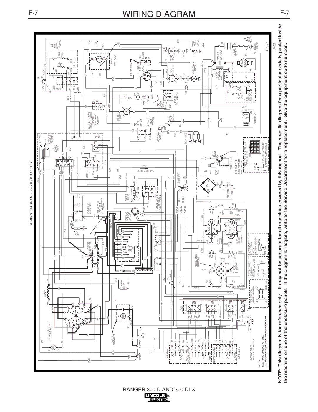
WIRING DIAGRAM - RANGER 300 DLX


F-7


254B

254A


3 TURNS


CB8


210


15A


L1


254


BLACK


BLACK


254C


222E


W6

(CHOKE)


W4


(-)

S1


IDLER WELD


222F


ELECTRODE POLARITY


SWITCH


W7


CURRENT


L2


VM


232


232


PC


SENSOR


222K


222J


5

10


HIGH


BOARD


222H


BLACK


SPEED


(+)


W5


PCB1


PULL


HOLD


240


240


SOLENOID


211


239

236


2C


COIL


COIL


224


CV-


J2

247


W3


4J10


WHITE


CV+


76


250


213B


245


+


77


222


213A

RED


214B


DC+


100


R1

RED

C2


C3

C4


C5


1

6


J11


214A


75


213


25W


5J10


W3


DC-


239


_


220


236A


221


AC


4

8


247


5F


W4


200B


W11


OUTPUT


31,000 MFD


WELDING TERMINAL


254B


214


221

220


254


(+) RECTIFIER


CAPACITORS


W7


J1

2


4


CONTROL SWITCH


5G


W14


201A


SHOWN IN


ON


-


W15


D1

W16

A1


235


A2


210


224


J3

5A

"ALWAYS ON"


S7


11J10


W10


W1


W12


S2A (CLOSED


(-)


POSITION


224F


WITH S2 IN


1

5

1


3


236


C1, C2, C3 OR C4


+

12J10


POSITION)


219


5F

222


W13


5C


W8


A2


224F


201A


REACTOR


ENGINE


254A

OUTPUT


224D


CONTACTOR


232


240


HOUR METER


A1


214


BATTERY


224E


R


200B


RANGER 300


25 OHM


W12


R1 R2 R3R4 R5 R6R7 C1C2 C3 C4


CHARGER


WIRING


CR1


R2


235


50W


IDLER AC


OUTPUT


77


R


224


241


W10


RANGE


CURRENT


RHEOSTAT

75


BLUE


W2


SENSOR


"SIG" TERMINAL


224C


W9


SWITCH


MAX

10K POT


W9


W1


S2


R3


75A


250

S5


15A

224C


CW


226


76D


FLASHING CURRENT


AUTO

IDLER


CB9


77D


FUEL


WORK

ELECTRODE


5A


SWITCH


FUEL


C4


235B BLUE235C


GND


76A


RED


GAUGE


SENDER


C3


6


5C


S

+


C2


S8

76


77


HIGH

SHOWN IN

227A

8J10


5W


21


C1


3


"HIGH"


235A

5G


STATOR


POSITION


21A

67


D AND 300 DLX


31

42


32

3

6

9


7


REMOTE SWITCH

76D


GLOW PLUG


S6


5B


DIAGRAM


2C


(SHOWN IN


S3


75A


5 GND-E


REMOTE POSITION)


SWITCH


ON/OFF


224H


76A


222G


SWITCH


224G


221C

235B


AMPHENOL 1


77A


77A


222


224E


CB1


2C


223A

S4


222C


J

31A


31A


(15AMP)


START


R

OIL


WATER

R


115VAC


224C


PRESSURE

TEMP.


A

32


5A


3J10

SWITCH


SHOWN IN


D

4A


5E


GND-E


5E


GROUND SCREW


"ON" POSITION


220A

220C


PCB2


GND-G


BLOWER BAFFLE


223

225


221A


CONTACTOR


C

2A


BYPASS PC


5A


GND-C


5B


222B


9J10


10J10


4

8


GND-D


GLOW PLUGS


WORK

H

21


5H


7J10

6J10


220B


2A


3


221B


REMOTE CONTROL


4C


E

77C

77C


J4


BLACK


OIL PRESSURE


WATER


F

76C

76C


SWITCH


TEMP.


125/250V. SINGLE


201


201A


75C

4A


RECEPTACLE


SWITCH


G

75C


I

31B


1

5


GREEN


BLACK

3E


BLACK

3F


7


222D


222E

42VAC


RED


K

42

75B

3

6


6


CB2


GREEN


D2


219


222B


B

GND-A

2B


GND-G


GND-D


120 V


9

AC

AC


(+)

(-)


222A


GROUND


50A


CB4


CB6


5


200B


1J10


77B


J5


225


J8


15A


J9


15A


SLIP


REMOTE CONTROL


76B


120/240V


3C


3D


200A


RINGS


STARTER


A

77B


BLACK


(+)


224B


76A


SILVER


RED

(+)


STARTER


B

76B

4B

1

4


3G


5L

5D


BLACK


SOLENOID


12


BLACKCB5

COLORED


3H


200


2J10


COIL


CONTACTOR

(+)


C

75B


BLACK

TERMINALS


RED


11


BLACK


D

2B


2

4


11

BLACK


BLACK


GREEN


(+)


(-)


5H


BLACK


CONTACTOR


76A


800 MFD


C1


RED


GND-C


120 V


E

4B


CB7


2C


J6


5D


ROTOR FIELD


WHITE


F

GND-B

75A


3


CB3


15A


J10


15A

3D


201


237


12 VOLT


GROUND


77A


SILVER


3C


227


(-)


77A

1

3


3A


50A

WHITE


3A


(-)


POSITIVE SLIP


COLORED


SILVER


WHITE

WHITE

3B


BATTERY


AMPHENOL 2


3B


TERM.


BLACK


5


RING NEAREST


HOLD

PULL


67


BLACK


COLORED


5L

BLACK


4C


BLACK


TERMINALS


LAMINATION


COIL

COIL


CRANK


21A


J7


B


222D


WHITE


ENGINE HARNESS CONNECTOR


IG


224A

L3


MOTOR

5K


5E


FUEL SHUTDOWN


ALTERNAT0R


TO PANEL HARNESS


L


FUEL

BLACK


FRAME


5A


J10


J13


SHUTDOWN


5K


GROUND SCREW


IDLER SOLENOID


SOLENOID


CONNECTION


9

10

11

12


SOLENOID


J12


GROUND


ABOVE AMPHENOL HOLE


(HARNESS LEAD END)


(HARNESS LEAD END)

BLOCK


1J10


ALTERNATOR


5H

ENGINE


213


222F


(HARNESS LEAD END)


5

6

7

8


237


224A


1

2

3

4


GROUND


NOTES:


5K


ELECTRICAL SYMBOLS PER E1537


224B


INDICATES JACK NUMBER


214


222G


227


ALL CASE FRONT COMPONENTS VIEWED FROM REAR.


J11


J12

J13


INDICATES CAVITY NUMBER


6-20-97


L10262


NOTE: This diagram is for reference only. It may not be accurate for all machines covered by this manual. The specific diagram for a particular code is pasted inside

F-7

the machine on one of the enclosure panels. If the diagram is illegible, write to the Service Department for a replacement. Give the equipment code number..


Page 47
Image 47
Lincoln Electric 300 DLX manual Wiring, Diagram, Ranger

300 DLX, 300 D specifications

The Lincoln Electric 300 D and 300 DLX are portable diesel engine-driven welding generators that stand out for their versatility, reliability, and advanced features tailored for industrial, commercial, and construction applications. These machines are part of Lincoln Electric's commitment to delivering high-quality welding power solutions that can withstand the rigors of demanding work environments.

One of the key features of the Lincoln Electric 300 D and 300 DLX is their powerful engine, capable of generating consistent and reliable welding output. The machines are equipped with a robust, air-cooled, four-cycle diesel engine that ensures long run times and excellent fuel efficiency, making them ideal for extended job sites where access to power sources may be limited.

Both models provide an impressive welding output range, with the ability to weld continuously at high amperage. This high amperage capability allows welders to tackle a wide variety of applications, including stick, TIG, and MIG welding. The 300 DLX model boasts enhanced features such as increased welding output, which caters to heavy-duty applications, while the 300 D remains a solid choice for standard applications.

In terms of technology, the 300 DLX incorporates advanced digital technology that enables optimal arc performance and increased control over welding parameters. This feature not only improves weld quality but also enhances the overall user experience. The intuitive user interface allows welders to easily navigate through settings, making adjustments quick and efficient.

Both models also offer exceptional durability. Their rugged construction is designed to endure harsh job site conditions, and they are built with weather-resistant enclosures to protect vital components from the elements. The large fuel tanks ensure that operators can work for extended periods without frequent refueling, further enhancing productivity.

Additionally, the 300 D and 300 DLX are equipped with a variety of output options, including 115V and 230V auxiliary power, which can be utilized for powering tools and other equipment on-site. This versatility makes these generators not just welders, but comprehensive power solutions for a wide array of tasks.

In summary, the Lincoln Electric 300 D and 300 DLX are exceptional diesel engine-driven welding generators that offer unmatched power, advanced technology, and rugged durability. Their capacity to deliver superior welding performance, combined with versatile power output options, makes them indispensable tools for professional welders in a multitude of industries. Whether it’s for heavy industrial tasks or on-job site convenience, these models meet and exceed the expectations of demanding professionals.