OPERATION | ||
|
|
|
AC/DC TIG (CONSTANT CURRENT) WELDING
1.Connect the
2.Refer to the instruction manual with the TIG module (IM
528)for operation with a RANGER 300. And proper machine settings.
3.Set the RANGE switch to the appropriate setting for the electrode you are using. Refer to
4.Set the POLARITY SWITCH to the desired polarity.
5.Do not AC TIG weld on the 250 AC range setting. The output current may exceed the rating of the RANGER 300.
6.Start the arc and begin welding.
NOTE: When using the RANGER 300 for AC TIG welding of aluminum, the TIG Module is to be set for CON-
TINUOUS HF.
AFTER YOU FINISH WELDING:
1.Stop the engine.
2.Allow the electrode and work to cool completely.
3.Remove the work clamp from the work.
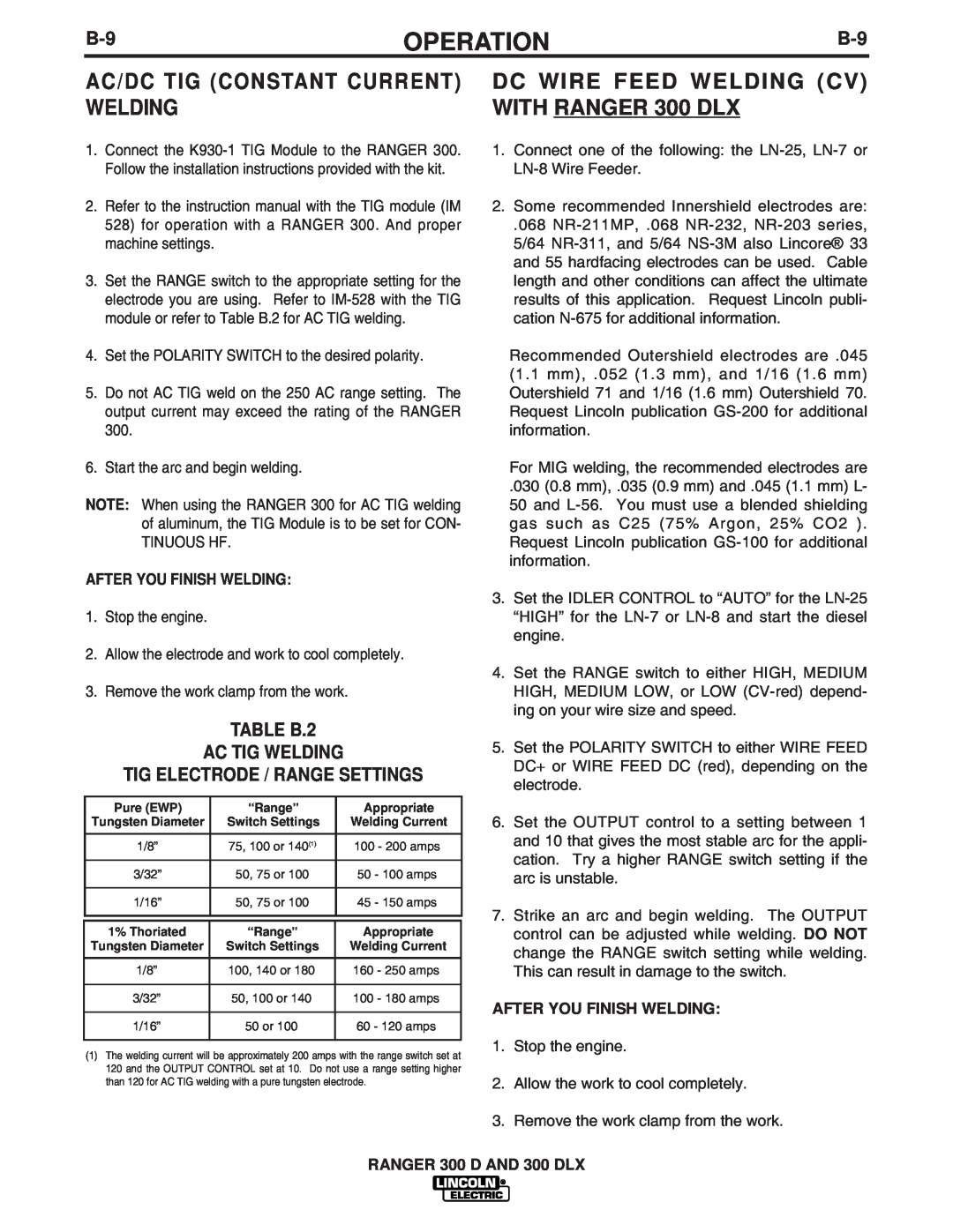
TABLE B.2
AC TIG WELDING
TIG ELECTRODE / RANGE SETTINGS
Pure (EWP) | “Range” | Appropriate |
Tungsten Diameter | Switch Settings | Welding Current |
|
|
|
1/8” | 75, 100 or 140(1) | 100 - 200 amps |
|
|
|
3/32” | 50, 75 or 100 | 50 - 100 amps |
|
|
|
1/16” | 50, 75 or 100 | 45 - 150 amps |
|
|
|
1% Thoriated | “Range” | Appropriate |
Tungsten Diameter | Switch Settings | Welding Current |
|
|
|
1/8” | 100, 140 or 180 | 160 - 250 amps |
|
|
|
3/32” | 50, 100 or 140 | 100 - 180 amps |
|
|
|
1/16” | 50 or 100 | 60 - 120 amps |
|
|
|
(1)The welding current will be approximately 200 amps with the range switch set at 120 and the OUTPUT CONTROL set at 10. Do not use a range setting higher than 120 for AC TIG welding with a pure tungsten electrode.
DC WIRE FEED WELDING (CV) WITH RANGER 300 DLX
1.Connect one of the following: the
2.Some recommended Innershield electrodes are:
.068
Recommended Outershield electrodes are .045 (1.1 mm), .052 (1.3 mm), and 1/16 (1.6 mm) Outershield 71 and 1/16 (1.6 mm) Outershield 70. Request Lincoln publication
For MIG welding, the recommended electrodes are
.030 (0.8 mm), .035 (0.9 mm) and .045 (1.1 mm) L- 50 and
3.Set the IDLER CONTROL to “AUTO” for the
4.Set the RANGE switch to either HIGH, MEDIUM HIGH, MEDIUM LOW, or LOW
5.Set the POLARITY SWITCH to either WIRE FEED DC+ or WIRE FEED DC (red), depending on the electrode.
6.Set the OUTPUT control to a setting between 1 and 10 that gives the most stable arc for the appli- cation. Try a higher RANGE switch setting if the arc is unstable.
7.Strike an arc and begin welding. The OUTPUT control can be adjusted while welding. DO NOT change the RANGE switch setting while welding. This can result in damage to the switch.
AFTER YOU FINISH WELDING:
1.Stop the engine.
2.Allow the work to cool completely.
3.Remove the work clamp from the work.
RANGER 300 D AND 300 DLX