|
|
|
| PARTS |
|
|
| 3 |
| ||
|
|
|
|
|
|
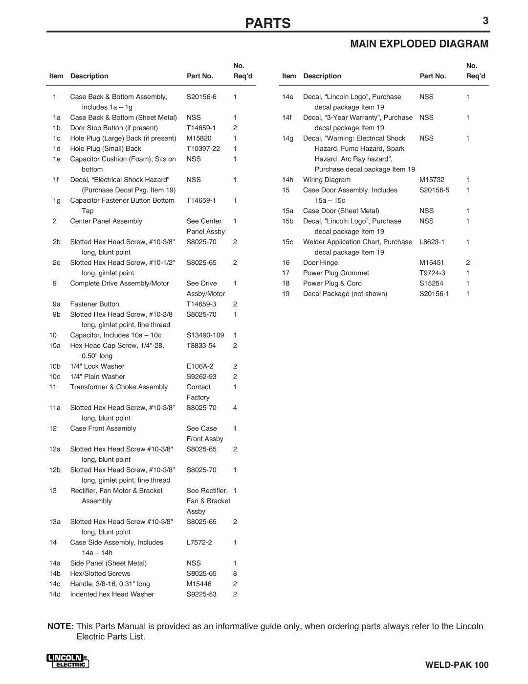
| MAIN EXPLODED DIAGRAM | ||||
|
|
|
| No. |
|
|
|
|
| No. | |
Item | Description | Part No. | Reqʼd |
| Item | Description | Part No. | Reqʼd | |||
|
|
|
|
|
|
|
|
|
| ||
1 | Case Back & Bottom Assembly, | 1 |
| 14e | Decal, “Lincoln Logo”, Purchase | NSS | 1 |
| |||
| Includes 1a – 1g |
|
|
|
| decal package Item 19 |
|
|
| ||
1a | Case Back & Bottom (Sheet Metal) | NSS | 1 |
| 14f | Decal, | NSS | 1 |
| ||
1b | Door Stop Button (if present) | 2 |
|
| decal package Item 19 |
|
|
| |||
1c | Hole Plug (Large) Back (if present) | M15820 | 1 |
| 14g | Decal, “Warning: Electrical Shock | NSS | 1 |
| ||
1d | Hole Plug (Small) Back | 1 |
|
| Hazard, Fume Hazard, Spark |
|
|
| |||
1e | Capacitor Cushion (Foam), Sits on | NSS | 1 |
|
| Hazard, Arc Ray hazard”, |
|
|
| ||
| bottom |
|
|
|
| Purchase decal package Item 19 |
|
|
| ||
1f | Decal, “Electrical Shock Hazard” | NSS | 1 |
| 14h | Wiring Diagram | M15732 | 1 |
| ||
| (Purchase Decal Pkg. Item 19) |
|
| 15 | Case Door Assembly, Includes | 1 |
| ||||
1g | Capacitor Fastener Button Bottom | 1 |
|
| 15a – 15c |
|
|
| |||
| Tap |
|
|
| 15a | Case Door (Sheet Metal) | NSS | 1 |
| ||
2 | Center Panel Assembly | See Center | 1 |
| 15b | Decal, “Lincoln Logo”, Purchase | NSS | 1 |
| ||
|
|
| Panel Assby |
|
|
| decal package Item 19 |
|
|
| |
2b | Slotted Hex Head Screw, | 2 |
| 15c | Welder Application Chart, Purchase | 1 |
| ||||
| long, blunt point |
|
|
|
| decal package Item 19 |
|
|
| ||
2c | Slotted Hex Head Screw, | 2 | 16 | Door Hinge | M15451 | 2 |
| ||||
| long, gimlet point |
|
| 17 | Power Plug Grommet | 1 |
| ||||
9 | Complete Drive Assembly/Motor | See Drive | 1 | 18 | Power Plug & Cord | S15254 | 1 |
| |||
|
|
| Assby/Motor |
| 19 | Decal Package (not shown) | 1 |
| |||
9a | Fastener Button | 2 |
|
|
|
|
|
|
| ||
9b | Slotted Hex Head Screw, | 1 |
|
|
|
|
|
|
| ||
| long, gimlet point, fine thread |
|
|
|
|
|
|
|
|
| |
10 | Capacitor, Includes 10a – 10c | 1 |
|
|
|
|
|
|
| ||
10a | Hex Head Cap Screw, | 2 |
|
|
|
|
|
|
| ||
| 0.50" long |
|
|
|
|
|
|
|
|
| |
10b | 1/4" Lock Washer | 2 |
|
|
|
|
|
|
| ||
10c | 1/4" Plain Washer | 2 |
|
|
|
|
|
|
| ||
11 | Transformer & Choke Assembly | Contact | 1 |
|
|
|
|
|
|
| |
|
|
| Factory |
|
|
|
|
|
|
|
|
11a | Slotted Hex Head Screw, | 4 |
|
|
|
|
|
|
| ||
| long, blunt point |
|
|
|
|
|
|
|
|
| |
12 | Case Front Assembly | See Case | 1 |
|
|
|
|
|
|
| |
|
|
| Front Assby |
|
|
|
|
|
|
|
|
12a | Slotted Hex Head Screw | 2 |
|
|
|
|
|
|
| ||
| long, blunt point |
|
|
|
|
|
|
|
|
| |
12b | Slotted Hex Head Screw, | 1 |
|
|
|
|
|
|
| ||
| long, gimlet point, fine thread |
|
|
|
|
|
|
|
|
| |
13 | Rectifier, Fan Motor & Bracket | See Rectifier, | 1 |
|
|
|
|
|
|
| |
| Assembly | Fan & Bracket |
|
|
|
|
|
|
|
| |
|
|
| Assby |
|
|
|
|
|
|
|
|
13a | Slotted Hex Head Screw | 2 |
|
|
|
|
|
|
| ||
| long, blunt point |
|
|
|
|
|
|
|
|
| |
14 | Case Side Assembly, Includes | 1 |
|
|
|
|
|
|
| ||
| 14a – 14h |
|
|
|
|
|
|
|
|
| |
14a | Side Panel (Sheet Metal) | NSS | 1 |
|
|
|
|
|
|
| |
14b | Hex/Slotted Screws | 8 |
|
|
|
|
|
|
| ||
14c | Handle, | M15446 | 2 |
|
|
|
|
|
|
| |
14d | Indented hex Head Washer | 2 |
|
|
|
|
|
|
| ||
NOTE: This Parts Manual is provided as an informative guide only, when ordering parts always refer to the Lincoln Electric Parts List.