MAINTENANCED-3
CHANGING DRIVE ROLL
The drive roll has two grooves; one for .023"
–.025" (0.6 mm) solid steel electrode and a larger knurled groove for .030" (0.8 mm) solid and .035" (0.9 mm)
If .023"
1.Connect the machine to its rated input power per instructions in Installation sec- tion.
2.Release the
3.Turn the power switch to ON (marked “I”).
4.Set the wire speed to minimum and jog the drive unit with the trigger switch until the drive roll set screw is facing up.
![]() CAUTION
CAUTION
When inching the welding wire, the drive rolls, gun connector block, and gun con- tact tip are energized relative to work and ground and remain energized for several seconds after the gun trigger is released.
5.Turn the power switch to OFF (marked “O”).
6.Loosen the drive roll set screw with the 5/64" (2.0 mm) hex wrench supplied.
7.Remove the drive roll, flip over and rein- stall with the .023
8.Push a length of straightened welding wire through the wire feeder guide tubes and adjust the position of the drive roll so that the groove is centered on the wire. Make certain the set screw is located on the flat portion of the shaft and tighten.
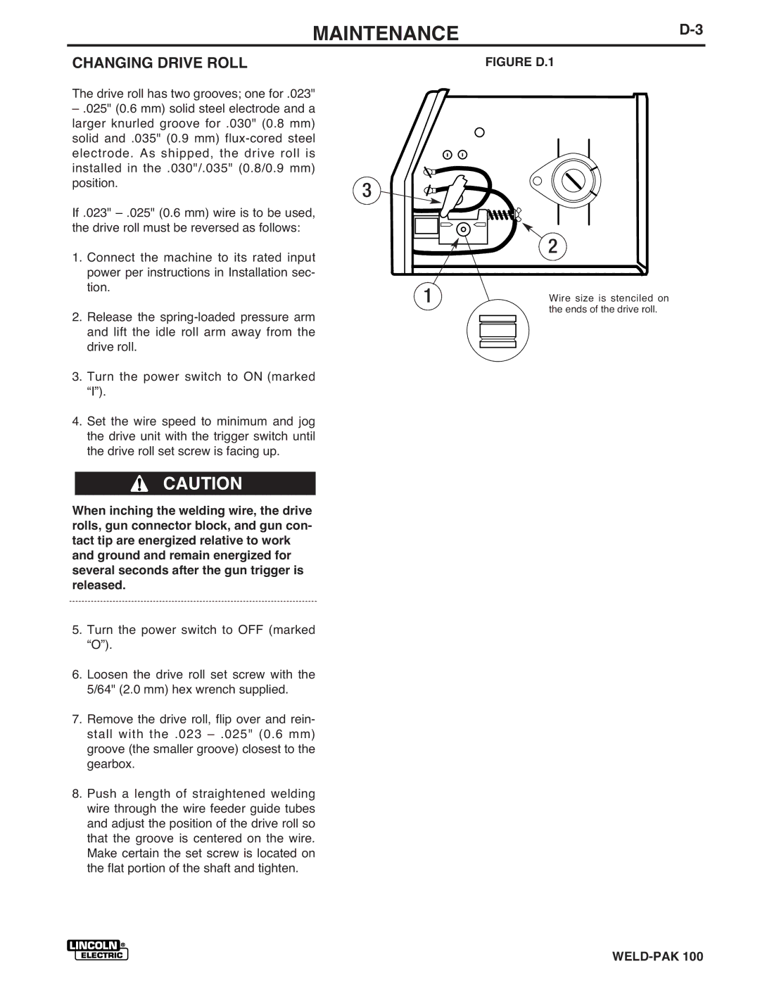
FIGURE D.1
3 ![]()
![]()
![]()
| 2 |
1 | Wire size is stenciled on |
| the ends of the drive roll. |