MAINTENANCE | |
GUN AND CAbLE MAINTENANCE |
|
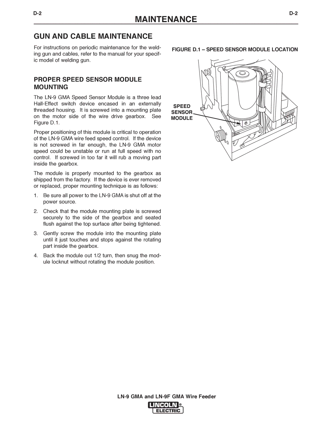
For instructions on periodic maintenance for the weld- | FIGURE D.1 – SPEED SENSOR MODULE LOCATION |
ing gun and cables, refer to the manual for your specif- |
|
ic model of welding gun. |
|
PROPER SPEED SENSOR MODULE |
|
MOUNTING |
|
The |
|
| |
threaded housing. It is screwed into a mounting plate |
|
on the motor side of the wire drive gearbox. See |
|
Figure D.1. |
|
Proper positioning of this module is critical to operation |
|
of the |
|
is not screwed in far enough, the |
|
speed could be unstable or run at full speed with no |
|
control. If screwed in too far it will rub a moving part |
|
inside the gearbox. |
|
The module is properly mounted to the gearbox as |
|
shipped from the factory. If the device is ever removed |
|
or replaced, proper mounting technique is as follows: |
|
1. Be sure all power to the |
|
power source. |
|
2. Check that the module mounting plate is screwed |
|
securely to the side of the gearbox and seated |
|
flush against the top surface after being tightened. |
|
3. Gently screw the module into the mounting plate |
|
until it just touches and stops against the rotating |
|
part inside the gearbox. |
|
4. Back the module out 1/2 turn, then snug the mod- |
|
ule locknut without rotating the module position. |
|