INSTALLATION
ROUTING THE ELECTRODE
The electrode supply may be either from reels, Readi- Reels, spools, or bulk packaged drums or reels. Observe the following precautions:
•The electrode must be routed to the wire feed unit so that the bends in the wire are at a minimum. The force required to pull the wire from the reel into the wire feed unit must be kept at a minimum.
•The electrode is "hot" when the gun trigger is pressed and must be insulated from the boom and structure.
•If more than one wire feed unit share the same boom, their wire and reels must be insulated from each other and insulated from their mounting struc- ture.
See the Accessories section for information about mounting a K299 wire reel assembly.
ELECTRICAL CONNECTIONS - LN-9 GMA AND LN-9F GMA
POWER INPUT CAbLE ASSEMbLY
A special cable assembly is required to connect all LN- 9 GMA models to the power source. The assembly includes control cable and electrode cable. Various sizes are available, based on length and maximum welding current. The following power source cable assemblies are available:
K196 for Terminal Strip control connection and output terminal.
K595 for
K596 for
NOTE: Use of an
CONNECTING THE POWER INPUT CAbLE ASSEMbLY TO THE
The K196, K595, or K596 cable assembly consists of an electrode cable and multiconductor control cable. The control cable has a polarized plug on the wire feeder end. To install:
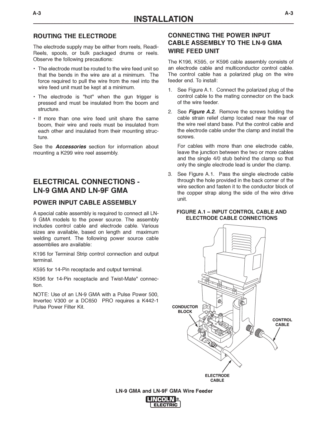
1.See Figure A.1. Connect the polarized plug of the control cable to the mating connector on the back of the wire feeder.
2.See Figure A.2. Remove the screws holding the cable strain relief clamp located near the rear of the wire reel stand base. Put the control cable and the electrode cable under the clamp and install the screws.
For cables with more than one electrode cable, leave the junction between the two or more cables and the single 4/0 stub behind the clamp so that only the single electrode lead is under the clamp.
3.See Figure A.1. Pass the single electrode cable through the hole provided in the back corner of the wire section and fasten it to the conductor block of the copper strap along the side of the wire drive unit.