MAINTENANCE
GUN CAbLE CONNECTOR REQUIRE-
MENTS TO PERMIT PROPER CONNEC- TION TO LINCOLN
The following Figures D.2 and D.3 should serve as a guide to determine if a particular gun or switch can be connected to the
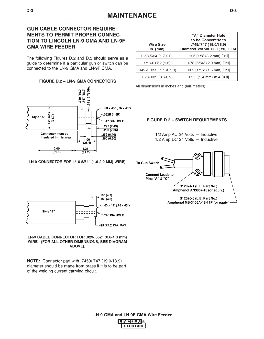
FIGURE D.2 – LN-9 GMA CONNECTORS
.749 (19.0) | .747 (18.9) | .62 (15.7) DIA. |
![]() .03 x 45° (.76 x 45°)
.03 x 45° (.76 x 45°)
max1.25 | (31.7) | .062R (1.5R) |
Style "A" |
|
|
|
| "A" DIA HOLE |
|
| .295 (7.49) | |
|
| .290 (7.36) | |
Connector must be |
| .252 (6.40) | |
insulated in this area |
| ||
1.00 | .260 (6.60) | ||
| |||
|
| ||
| (25.4) |
| |
2.00 | 1.25 |
| |
(51.0) | (31.7) |
|
.180 (4.5)
.160 (4.0)
![]() .03 x 45° (.76 x 45°)
.03 x 45° (.76 x 45°)
Style "B"
![]() "A" DIA HOLE
"A" DIA HOLE
.495 (12.5) DIA. MAX.
WIRE (FOR ALL OTHER DIMENSIONS, SEE DIAGRAM
AbOVE).
|
| “A” Diameter Hole |
|
| to be Concentric to |
Wire Size | .749/.747 (19.0/18.9) | |
in. (mm) | Diameter Within .008 (.20) F.I.M. | |
.125 [1/8” (3.2 mm) Drill] | ||
|
| |
.078 [5/64” (2.0 mm) Drill] | ||
.045 & .052 | (1.1 & 1.3) | .062 [1/16” (1.6 mm) Drill] |
.055 [(1.4 mm) #54 Drill] | ||
|
|
|
All dimensions in inches and (millimeters).
FIGURE D.2 – SWITCH REQUIREMENTS
1/2 Amp AC 24 Volts — Inductive
1/2 Amp DC 24 Volts — Inductive
To Gun Switch
Connect Leads to
Pins "A" & "C"
Amphenol
Amphenol
NOTE: Connector part with .7459/.747 (19.0/18.9) diameter should be made from brass if it is to be part of the welding current carrying circuit.