INSTALLATION
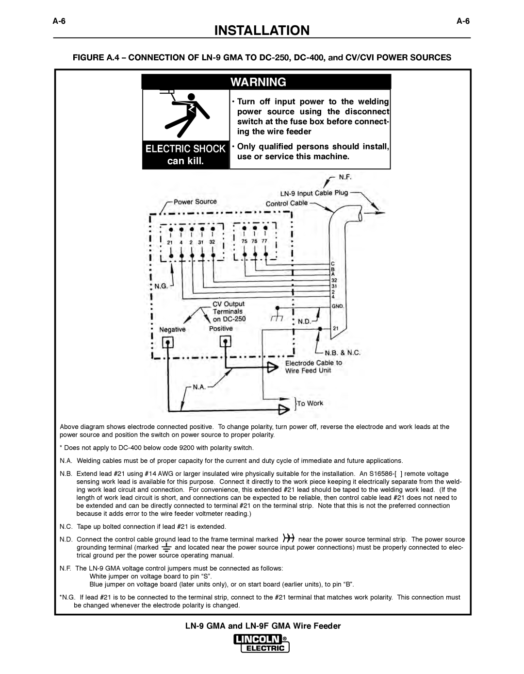
FIGURE A.4 – CONNECTION OF LN-9 GMA TO DC-250, DC-400, and CV/CVI POWER SOURCES
ELECTRIC SHOCK
can kill.
WARNING
•Turn off input power to the welding power source using the disconnect switch at the fuse box before connect- ing the wire feeder
•Only qualified persons should install, use or service this machine.
Above diagram shows electrode connected positive. To change polarity, turn power off, reverse the electrode and work leads at the power source and position the switch on power source to proper polarity.
* Does not apply to
N.A. Welding cables must be of proper capacity for the current and duty cycle of immediate and future applications.
N.B. Extend lead #21 using #14 AWG or larger insulated wire physically suitable for the installation. An
N.C. Tape up bolted connection if lead #21 is extended.
N.D. Connect the control cable ground lead to the frame terminal marked | near the power source terminal strip. The power source | |
grounding terminal (marked | and located near the power source input power connections) must be properly connected to elec- | |
trical ground per the power source operating manual. |
| |
N.F. The
White jumper on voltage board to pin “S”.
Blue jumper on voltage board (later units only), or on start board (earlier units), to pin “B”.
*N.G. If lead #21 is to be connected to the terminal strip, connect to the #21 terminal that matches work polarity. This connection must be changed whenever the electrode polarity is changed.