INSTALLATION
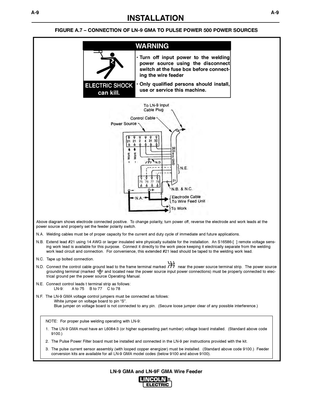
FIGURE A.7 – CONNECTION OF LN-9 GMA TO PULSE POWER 500 POWER SOURCES
ELECTRIC SHOCK
can kill.
WARNING
•Turn off input power to the welding power source using the disconnect switch at the fuse box before connect- ing the wire feeder
•Only qualified persons should install, use or service this machine.
75 76 77 78
Above diagram shows electrode connected positive. To change polarity, turn power off, reverse the electrode and work leads at the power source and properly set the feeder polarity switch.
N.A. Welding cables must be of proper capacity for the current and duty cycle of immediate and future applications.
N.B. Extend lead #21 using 14 AWG or larger insulated wire physically suitable for the installation. An
N.C. Tape up bolted connection.
N.D. Connect the control cable ground lead to the frame terminal marked![]() near the power source terminal strip. The power source
near the power source terminal strip. The power source
grounding terminal (marked ![]() and located near the power source input power connections) must be properly connected to elec- trical ground per the power source Operating Manual.
and located near the power source input power connections) must be properly connected to elec- trical ground per the power source Operating Manual.
N.E. Connect control leads t terminal strip as follows:
N.F. The
Blue jumper on voltage board is not connected to any pin. (Secure loose jumper clear of any possible interference.)
NOTE: For proper pulse welding operating with
1.The
2.The Pulse Power Filter board must be installed and connected in the
3.The pulse current sensor assembly (with looped copper energizer) must be installed. (Standard above code 9100.) Feeder conversion kits are available for all