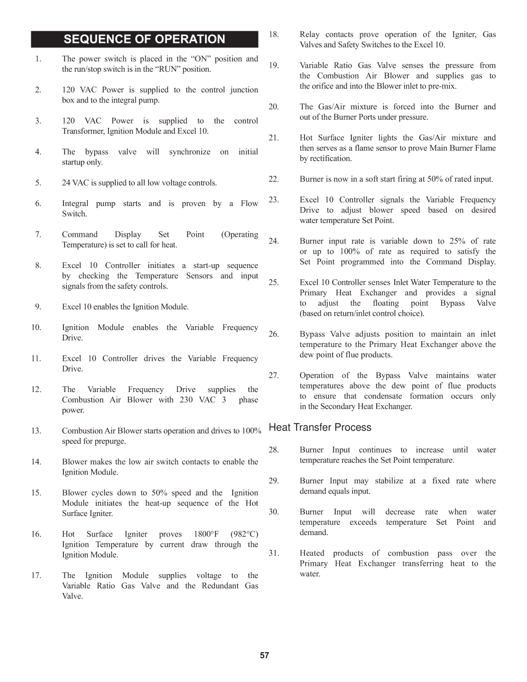
SEQUENCE OF OPERATION

1.The power switch is placed in the “ON” position and the run/stop switch is in the “RUN” position.

2.120 VAC Power is supplied to the control junction box and to the integral pump.

3.120 VAC Power is supplied to the control Transformer, Ignition Module and Excel 10.

4.The bypass valve will synchronize on initial startup only.

5.24 VAC is supplied to all low voltage controls.

6.Integral pump starts and is proven by a Flow Switch.

7.Command Display Set Point (Operating Temperature) is set to call for heat.

8.

Excel 10 Controller initiates

a start-up sequence


by checking the Temperature

Sensors and input


signals from the safety controls.


9.Excel 10 enables the Ignition Module.

10.Ignition Module enables the Variable Frequency Drive.

11.Excel 10 Controller drives the Variable Frequency Drive.

12.The Variable Frequency Drive supplies the

Combustion Air Blower with 230 VAC 3 phase power.

18.Relay contacts prove operation of the Igniter, Gas Valves and Safety Switches to the Excel 10.

19.Variable Ratio Gas Valve senses the pressure from

the Combustion Air Blower and supplies gas to the orifice and into the Blower inlet to pre-mix.

20.The Gas/Air mixture is forced into the Burner and out of the Burner Ports under pressure.

21.Hot Surface Igniter lights the Gas/Air mixture and then serves as a flame sensor to prove Main Burner Flame by rectification.

22.Burner is now in a soft start firing at 50% of rated input.

23.Excel 10 Controller signals the Variable Frequency Drive to adjust blower speed based on desired water temperature Set Point.

24.

Burner input rate is variable

down to 25% of rate


or

up to 100% of rate as

required to satisfy the


Set

Point programmed into

the Command Display.

25.Excel 10 Controller senses Inlet Water Temperature to the

Primary Heat Exchanger

and provides a

signal

to adjust the floating

point Bypass

Valve

(based on return/inlet control choice).


26.Bypass Valve adjusts position to maintain an inlet temperature to the Primary Heat Exchanger above the dew point of flue products.

27.Operation of the Bypass Valve maintains water

temperatures

above the dew

point of

flue products

to ensure

that condensate

formation

occurs only

in the Secondary Heat Exchanger.


13.Combustion Air Blower starts operation and drives to 100% speed for prepurge.

14.Blower makes the low air switch contacts to enable the Ignition Module.

15.Blower cycles down to 50% speed and the Ignition Module initiates the heat-up sequence of the Hot Surface Igniter.

16.Hot Surface Igniter proves 1800°F (982°C) Ignition Temperature by current draw through the Ignition Module.

17.The Ignition Module supplies voltage to the Variable Ratio Gas Valve and the Redundant Gas Valve.

Heat Transfer Process

28.Burner Input continues to increase until water temperature reaches the Set Point temperature.

29.Burner Input may stabilize at a fixed rate where demand equals input.

30.Burner Input will decrease rate when water temperature exceeds temperature Set Point and demand.

31.Heated products of combustion pass over the Primary Heat Exchanger transferring heat to the water.

57

Page 57
Image 57
Lochinvar 1, 000 through 2 warranty Sequence of Operation, Heat Transfer Process

000, 000 through 2, 1 specifications

Lochinvar 1 is a remarkable achievement in the realm of modern technology and engineering. As a powerful and efficient water heater, it has been designed to cater to a wide range of residential and commercial needs. One of the standout features of Lochinvar 1 is its advanced heating technology, which incorporates a high-efficiency condensing design. This technology allows the unit to achieve impressive energy savings by maximizing heat transfer while minimizing energy consumption.

The Lochinvar 1 utilizes a stainless steel heat exchanger that enhances durability and corrosion resistance. This not only extends the lifespan of the unit but also ensures consistent performance over time. Coupled with a user-friendly control system, users can easily adjust settings and monitor performance, enhancing overall convenience and usability.

Another key characteristic of the Lochinvar 1 is its compact design, making it suitable for a variety of installation environments. Whether in a residential basement or a commercial utility room, the unit’s space-saving configuration allows for efficient use of available area without compromising on capability.

Safety features are integral to the Lochinvar 1, providing peace of mind for users. The unit is equipped with advanced monitoring systems that can detect irregularities and automatically shut down the system if necessary. This not only protects the equipment but also enhances the safety of the environment in which it operates.

In terms of performance, Lochinvar 1 boasts a high recovery rate, ensuring hot water is available on demand. This is particularly beneficial for settings with high water usage, allowing simultaneous operations without lag.

Moreover, the unit supports various venting options, offering flexibility during installation. Whether using traditional vertical venting or innovations like direct venting, Lochinvar 1 accommodates different building designs and local codes, making it highly versatile.

In conclusion, Lochinvar 1 epitomizes the melding of efficiency, reliability, and user-friendly technology. With its high-performance features, robust safety systems, and adaptable installation options, it stands out as a forefront player in the water heating industry, meeting the diverse needs of today's consumers and businesses alike.