The installed sidewall vent cap assembly may be painted to match the exterior color. The opening through the wall for installation of the sidewall vent cap must provide an air space clearance of 2 inches (5.1 cm) around the flue pipe. The diameter of the opening for installation of the sidewall cap will be 4 inches (10.2 cm) larger (minimum) than the nominal diameter of the installed vent pipe to the sidewall cap.

The sidewall cap is installed from the outside and mounted to the wall with four screws or wall anchors. Seal under the screw heads with caulking. Install the screen assembly using the stainless steel screws provided in the kit. Install the Category IV vent pipe from the appliance to the vent cap. The installed vent pipe must protrude at least 2 inches (5.1 cm) into the screen area beyond the thimble portion of the sidewall cap assembly. See detailed instructions packed with the sidewall vent kit.

Follow all requirements in the General Category IV Venting sections for venting flue products to the outdoors. See the Combustion and Ventilation Air Requirements section to ensure that adequate combustion and ventilation air is supplied to the equipment room. All other general installation requirements must be followed.

LOCATION OF A SIDEWALL

VENT TERMINATION

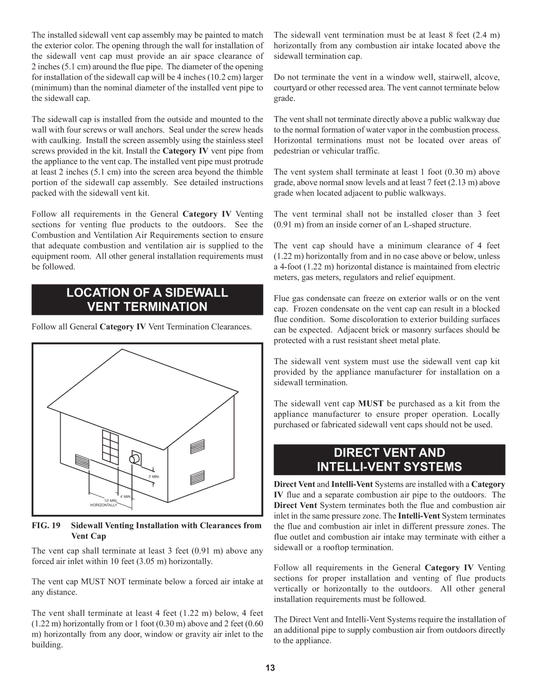
Follow all General Category IV Vent Termination Clearances.

3' MIN.

4' MIN.

10' MIN.

HORIZONTALLY

FIG. 19 Sidewall Venting Installation with Clearances from Vent Cap

The vent cap shall terminate at least 3 feet (0.91 m) above any forced air inlet within 10 feet (3.05 m) horizontally.

The vent cap MUST NOT terminate below a forced air intake at any distance.

The vent shall terminate at least 4 feet (1.22 m) below, 4 feet (1.22 m) horizontally from or 1 foot (0.30 m) above and 2 feet (0.60

m)horizontally from any door, window or gravity air inlet to the building.

The sidewall vent termination must be at least 8 feet (2.4 m) horizontally from any combustion air intake located above the sidewall termination cap.

Do not terminate the vent in a window well, stairwell, alcove, courtyard or other recessed area. The vent cannot terminate below grade.

The vent shall not terminate directly above a public walkway due to the normal formation of water vapor in the combustion process. Horizontal terminations must not be located over areas of pedestrian or vehicular traffic.

The vent system shall terminate at least 1 foot (0.30 m) above grade, above normal snow levels and at least 7 feet (2.13 m) above grade when located adjacent to public walkways.

The vent terminal shall not be installed closer than 3 feet (0.91 m) from an inside corner of an L-shaped structure.

The vent cap should have a minimum clearance of 4 feet (1.22 m) horizontally from and in no case above or below, unless a 4-foot (1.22 m) horizontal distance is maintained from electric meters, gas meters, regulators and relief equipment.

Flue gas condensate can freeze on exterior walls or on the vent cap. Frozen condensate on the vent cap can result in a blocked flue condition. Some discoloration to exterior building surfaces can be expected. Adjacent brick or masonry surfaces should be protected with a rust resistant sheet metal plate.

The sidewall vent system must use the sidewall vent cap kit provided by the appliance manufacturer for installation on a sidewall termination.

The sidewall vent cap MUST be purchased as a kit from the appliance manufacturer to ensure proper operation. Locally purchased or fabricated sidewall vent caps should not be used.

DIRECT VENT AND

INTELLI-VENT SYSTEMS

Direct Vent and Intelli-VentSystems are installed with a Category IV flue and a separate combustion air pipe to the outdoors. The Direct Vent System terminates both the flue and combustion air inlet in the same pressure zone. The Intelli-VentSystem terminates the flue and combustion air inlet in different pressure zones. The flue outlet and combustion air intake may terminate with either a sidewall or a rooftop termination.

Follow all requirements in the General Category IV Venting sections for proper installation and venting of flue products vertically or horizontally to the outdoors. All other general installation requirements must be followed.

The Direct Vent and Intelli-Vent Systems require the installation of an additional pipe to supply combustion air from outdoors directly to the appliance.

13

Page 13
Image 13
Lochinvar 000 through 2, 1 warranty Location of a Sidewall Vent Termination, Direct Vent INTELLI-VENT Systems

000, 000 through 2, 1 specifications

Lochinvar 1 is a remarkable achievement in the realm of modern technology and engineering. As a powerful and efficient water heater, it has been designed to cater to a wide range of residential and commercial needs. One of the standout features of Lochinvar 1 is its advanced heating technology, which incorporates a high-efficiency condensing design. This technology allows the unit to achieve impressive energy savings by maximizing heat transfer while minimizing energy consumption.

The Lochinvar 1 utilizes a stainless steel heat exchanger that enhances durability and corrosion resistance. This not only extends the lifespan of the unit but also ensures consistent performance over time. Coupled with a user-friendly control system, users can easily adjust settings and monitor performance, enhancing overall convenience and usability.

Another key characteristic of the Lochinvar 1 is its compact design, making it suitable for a variety of installation environments. Whether in a residential basement or a commercial utility room, the unit’s space-saving configuration allows for efficient use of available area without compromising on capability.

Safety features are integral to the Lochinvar 1, providing peace of mind for users. The unit is equipped with advanced monitoring systems that can detect irregularities and automatically shut down the system if necessary. This not only protects the equipment but also enhances the safety of the environment in which it operates.

In terms of performance, Lochinvar 1 boasts a high recovery rate, ensuring hot water is available on demand. This is particularly beneficial for settings with high water usage, allowing simultaneous operations without lag.

Moreover, the unit supports various venting options, offering flexibility during installation. Whether using traditional vertical venting or innovations like direct venting, Lochinvar 1 accommodates different building designs and local codes, making it highly versatile.

In conclusion, Lochinvar 1 epitomizes the melding of efficiency, reliability, and user-friendly technology. With its high-performance features, robust safety systems, and adaptable installation options, it stands out as a forefront player in the water heating industry, meeting the diverse needs of today's consumers and businesses alike.