Inlet and Outlet Connections

For ease of service, install unions on inlet and outlet of the appliance. The connection to the appliance marked “Inlet” on the header should be used for return from the system. The connection on the header marked “Outlet” is to be connected to the supply side of the system.

Minimum Pipe Size Requirements

Minimum water pipe connections to this appliance is 3 inch (76.2 mm) pipe for single unit installations installed not more than 70 equivalent feet (21.3 m) of pipe from the main system loop or storage tank. The equivalent number of straight feet of pipe for each valve and fitting in the connecting piping must be considered to properly arrive at the total equivalent feet of straight pipe in the field installed piping to the appliance. See the piping requirements in the heating boiler or water heater section of this manual. Consult factory if longer piping distances are required for a specific application.

the movement of the flue products over the finned copper surface and increase heat transfer. Water enters the primary heat exchanger and makes four passes over the area exposed to direct heat from the burner. An internal circulating pump ensures proper water flow over the heat transfer surfaces during burner operation. Water temperatures in the primary heat exchanger are controlled by the operation of the automatic bypass assembly. Operation of the bypass maintains water temperatures above 130°F (54.4°C) in the primary heat exchanger to prevent flue gas condensation on the primary heat exchanger surfaces.

SECONDARY HEAT EXCHANGER

PRIMARY HEAT EXCHANGER

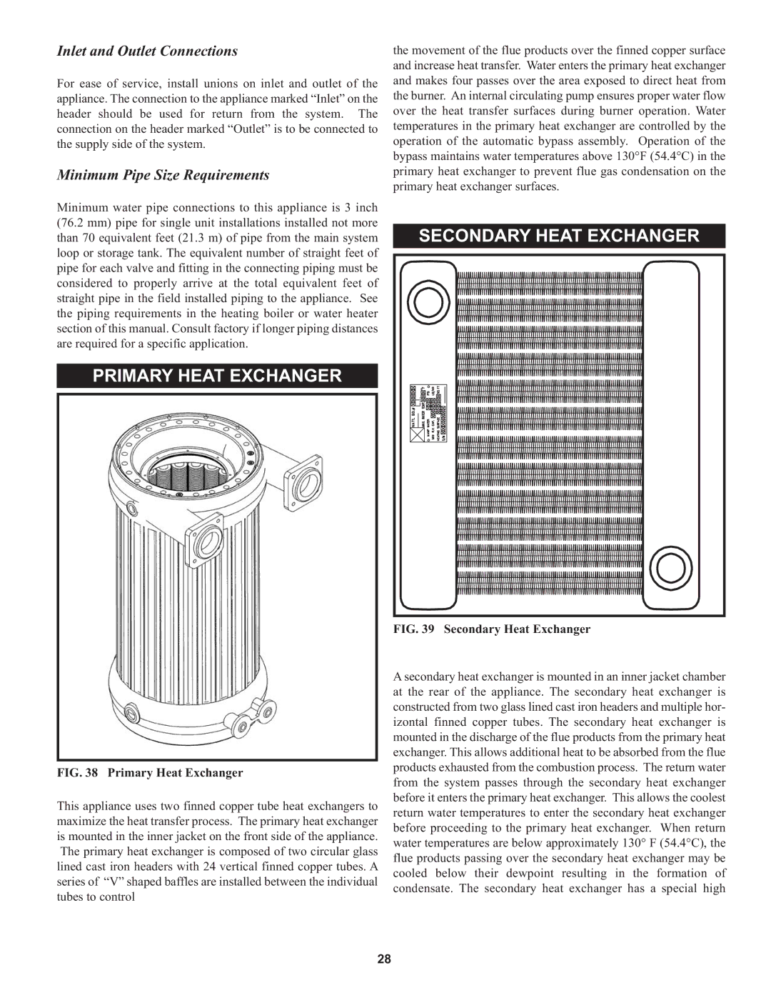
FIG. 38 Primary Heat Exchanger

This appliance uses two finned copper tube heat exchangers to maximize the heat transfer process. The primary heat exchanger is mounted in the inner jacket on the front side of the appliance. The primary heat exchanger is composed of two circular glass lined cast iron headers with 24 vertical finned copper tubes. A series of “V” shaped baffles are installed between the individual tubes to control

FIG. 39 Secondary Heat Exchanger

A secondary heat exchanger is mounted in an inner jacket chamber at the rear of the appliance. The secondary heat exchanger is constructed from two glass lined cast iron headers and multiple hor- izontal finned copper tubes. The secondary heat exchanger is mounted in the discharge of the flue products from the primary heat exchanger. This allows additional heat to be absorbed from the flue products exhausted from the combustion process. The return water from the system passes through the secondary heat exchanger before it enters the primary heat exchanger. This allows the coolest return water temperatures to enter the secondary heat exchanger before proceeding to the primary heat exchanger. When return water temperatures are below approximately 130° F (54.4°C), the flue products passing over the secondary heat exchanger may be cooled below their dewpoint resulting in the formation of condensate. The secondary heat exchanger has a special high

28

Page 28
Image 28
Lochinvar 000 through 2, 1 warranty Secondary Heat Exchanger Primary Heat Exchanger, Inlet and Outlet Connections

000, 000 through 2, 1 specifications

Lochinvar 1 is a remarkable achievement in the realm of modern technology and engineering. As a powerful and efficient water heater, it has been designed to cater to a wide range of residential and commercial needs. One of the standout features of Lochinvar 1 is its advanced heating technology, which incorporates a high-efficiency condensing design. This technology allows the unit to achieve impressive energy savings by maximizing heat transfer while minimizing energy consumption.

The Lochinvar 1 utilizes a stainless steel heat exchanger that enhances durability and corrosion resistance. This not only extends the lifespan of the unit but also ensures consistent performance over time. Coupled with a user-friendly control system, users can easily adjust settings and monitor performance, enhancing overall convenience and usability.

Another key characteristic of the Lochinvar 1 is its compact design, making it suitable for a variety of installation environments. Whether in a residential basement or a commercial utility room, the unit’s space-saving configuration allows for efficient use of available area without compromising on capability.

Safety features are integral to the Lochinvar 1, providing peace of mind for users. The unit is equipped with advanced monitoring systems that can detect irregularities and automatically shut down the system if necessary. This not only protects the equipment but also enhances the safety of the environment in which it operates.

In terms of performance, Lochinvar 1 boasts a high recovery rate, ensuring hot water is available on demand. This is particularly beneficial for settings with high water usage, allowing simultaneous operations without lag.

Moreover, the unit supports various venting options, offering flexibility during installation. Whether using traditional vertical venting or innovations like direct venting, Lochinvar 1 accommodates different building designs and local codes, making it highly versatile.

In conclusion, Lochinvar 1 epitomizes the melding of efficiency, reliability, and user-friendly technology. With its high-performance features, robust safety systems, and adaptable installation options, it stands out as a forefront player in the water heating industry, meeting the diverse needs of today's consumers and businesses alike.