RELIEF VALVE

This unit is supplied with a relief valve(s) sized in accordance with ASME Boiler and Pressure Vessel Code, Section IV (“Heating Boilers”). The relief valve(s) is installed in the vertical position and mounted in the hot water outlet. No valve is to be placed between the relief valve, and the unit. To prevent water damage, the discharge from the relief valve shall be piped to a suitable floor drain for disposal when relief occurs. No reducing couplings or other restrictions shall be installed in the discharge line. The discharge line shall allow complete drainage of the valve and line. Relief valves should be manually operated at least once a year.

CAUTION￿

Avoid contact with hot discharge water.

NOTE:

The gas train and controls assembly provided on this unit have been tested under the applicable American National Standard to meet minimum safety and performance criteria such as safe lighting, combustion and safety shutdown operation.

air blower. The valve is a 1:1 differential pressure air/gas ratio controller. The valve adjusts the same pressure difference on the gas side as it senses on the air side. The valve performs the functions of safety shutoff, constant pressure regulation and air/gas ratio control. Slow opening and safety shutoff is accomplished by operation of an electro hydraulic cylinder. Full closing of the valve seat occurs in less than 0.8 seconds when the valve is de-energized. A visual stroke position indicator is provided on the valve assembly to indicate the position of the valve seat. Operation of the gas valve in combination with the combustion air blower allows the burner input rate to vary from 25% to 100% based on temperature demand. There is no need for an additional upstream constant gas pressure regulator internally to the appliance as long as the gas supply is maintained within the specified minimum and maximum pressures.

The manifold pressure is preset at the factory and adjustment is not usually required if gas supply pressure is maintained within the specified range. If the manifold pressure is to be measured, follow the “Gas Manifold Pressure Measurement Procedure” for proper measurement.

There are no serviceable parts on the ratio gas valve actuator.

DIAPHRAGM GAS VALVE

RATIO GAS VALVE

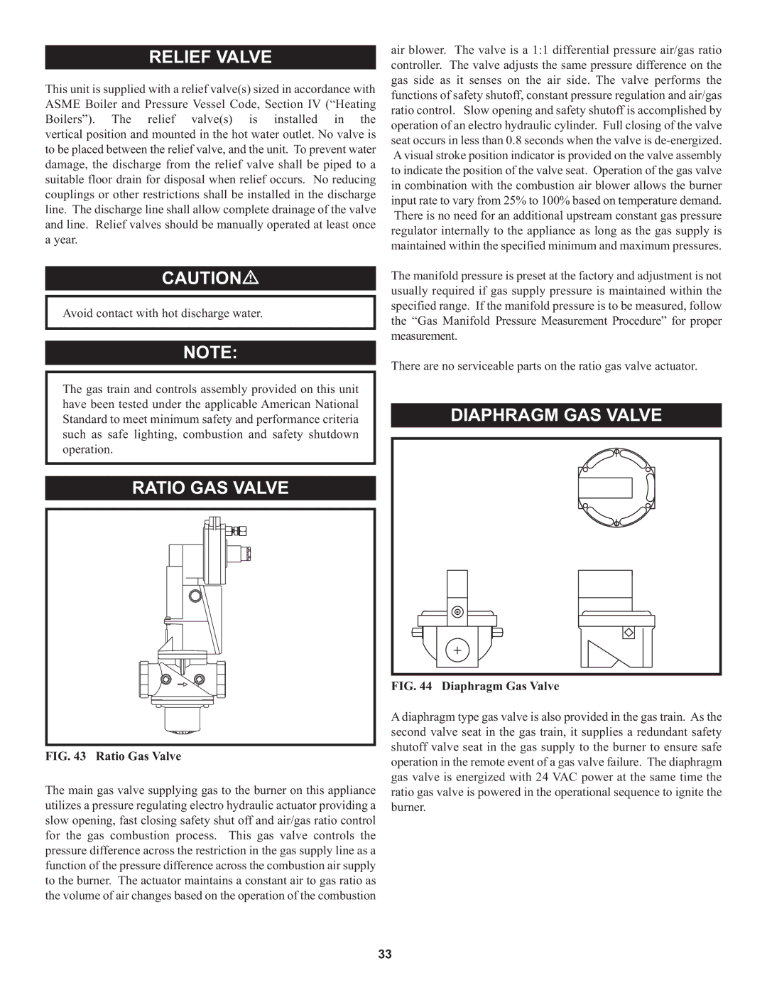
FIG. 43 Ratio Gas Valve

The main gas valve supplying gas to the burner on this appliance utilizes a pressure regulating electro hydraulic actuator providing a slow opening, fast closing safety shut off and air/gas ratio control for the gas combustion process. This gas valve controls the pressure difference across the restriction in the gas supply line as a function of the pressure difference across the combustion air supply to the burner. The actuator maintains a constant air to gas ratio as the volume of air changes based on the operation of the combustion

FIG. 44 Diaphragm Gas Valve

A diaphragm type gas valve is also provided in the gas train. As the second valve seat in the gas train, it supplies a redundant safety shutoff valve seat in the gas supply to the burner to ensure safe operation in the remote event of a gas valve failure. The diaphragm gas valve is energized with 24 VAC power at the same time the ratio gas valve is powered in the operational sequence to ignite the burner.

33

Page 33
Image 33
Lochinvar 1, 000 through 2 warranty Relief Valve, Diaphragm GAS Valve Ratio GAS Valve

000, 000 through 2, 1 specifications

Lochinvar 1 is a remarkable achievement in the realm of modern technology and engineering. As a powerful and efficient water heater, it has been designed to cater to a wide range of residential and commercial needs. One of the standout features of Lochinvar 1 is its advanced heating technology, which incorporates a high-efficiency condensing design. This technology allows the unit to achieve impressive energy savings by maximizing heat transfer while minimizing energy consumption.

The Lochinvar 1 utilizes a stainless steel heat exchanger that enhances durability and corrosion resistance. This not only extends the lifespan of the unit but also ensures consistent performance over time. Coupled with a user-friendly control system, users can easily adjust settings and monitor performance, enhancing overall convenience and usability.

Another key characteristic of the Lochinvar 1 is its compact design, making it suitable for a variety of installation environments. Whether in a residential basement or a commercial utility room, the unit’s space-saving configuration allows for efficient use of available area without compromising on capability.

Safety features are integral to the Lochinvar 1, providing peace of mind for users. The unit is equipped with advanced monitoring systems that can detect irregularities and automatically shut down the system if necessary. This not only protects the equipment but also enhances the safety of the environment in which it operates.

In terms of performance, Lochinvar 1 boasts a high recovery rate, ensuring hot water is available on demand. This is particularly beneficial for settings with high water usage, allowing simultaneous operations without lag.

Moreover, the unit supports various venting options, offering flexibility during installation. Whether using traditional vertical venting or innovations like direct venting, Lochinvar 1 accommodates different building designs and local codes, making it highly versatile.

In conclusion, Lochinvar 1 epitomizes the melding of efficiency, reliability, and user-friendly technology. With its high-performance features, robust safety systems, and adaptable installation options, it stands out as a forefront player in the water heating industry, meeting the diverse needs of today's consumers and businesses alike.